3.6 LOGIC REPRESENTATIONS AND CIRCUIT DESIGN
Logic gates are used to represent and implement logic expression into digital circuit diagrams. Consider the following logic function:
![]()
The digital circuit (Figure 3.4) implements the function f. The digital circuit consists of elementary logic functions, which are implicit in the logic function. The conversion from logic expressions to circuit diagrams obeys the operator precedence rules shown in Figure 3.5. These precedence rules dictate the order in which the implicit elementary logic functions are implemented.
Notice that logic expressions within parentheses are converted first. The implementation of the elementary logic functions within the parentheses obeys the precedence rules as well. In all cases, the NOT function is implemented first, then the AND function, then the OR function. Similarly, a digital circuit can be converted to a logic expression. The logic function of the digital circuit is found by propagating the input variables through the gates to the output of the circuit. The logic output expression of a gate is determined by the logic expressions at its inputs. Consider the digital circuit shown in Figure 3.6. The logic expression, which represents the logic circuit diagram in Figure 3.6, is expressed as
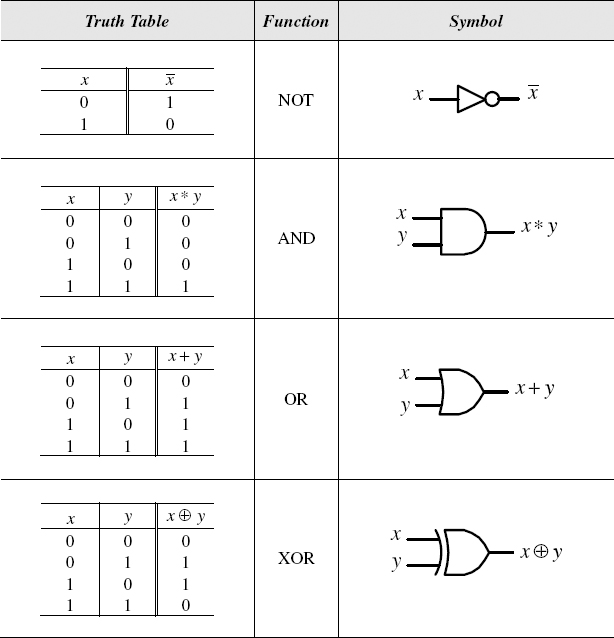
Figure 3.1 NOT, ...
Get Introduction to Digital Systems: Modeling, Synthesis, and Simulation Using VHDL now with the O’Reilly learning platform.
O’Reilly members experience books, live events, courses curated by job role, and more from O’Reilly and nearly 200 top publishers.

