Now we will interface L293D with Raspberry Pi as shown in the following diagram:
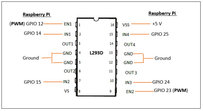
Figure 8.8
In the previous diagram:
- GPIO 12 of Raspberry Pi is connected to enable 1 (pin 1) of L293D
- GPIO 14 of Raspberry Pi is connected to input 1 (pin 2) of L293D
- GPIO 15 of Raspberry Pi is connected to input 2 (pin 7) of L293D
- GPIO 23 of Raspberry Pi is connected to enable 2 (pin 9) of L293D
- GPIO 24 of Raspberry Pi is connected to input 3 (pin 10) of L293D
- GPIO 25 of Raspberry Pi is connected to input 4 (pin 15) of L293D
- VSS of L293D is connected to 5V output from Raspberry Pi
- GND of L293D is connected to ground terminal of ...

