First we interface both the motor of car with motor driver IC L293D as shown in the following diagram:
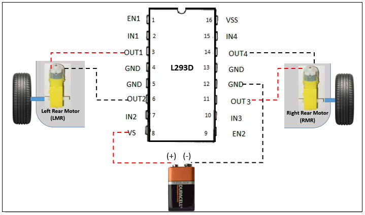
Figure 8.7
In the previous diagram:
- OUT1 (pin 3) has been connected to one terminal of LRM
- OUT2 (pin 6) has been connected to second terminal of LRM
- OUT3 (pin 11) has been connected to one terminal of RRM
- OUT4 (pin 14) has been connected to second terminal of RRM
- VS is connected to positive terminal of 9V DC battery
- GND is connected to negative terminal of 9V DC battery
The OUT pins provide DC output voltage to drive the motor. The value of voltage output of out pins is decided by the voltage applied to pin VS of ...

