Configuring the hardware
Let's now configure the hardware for this project. The configuration for this project is quite complex, which was why I included a schematic to help you out:
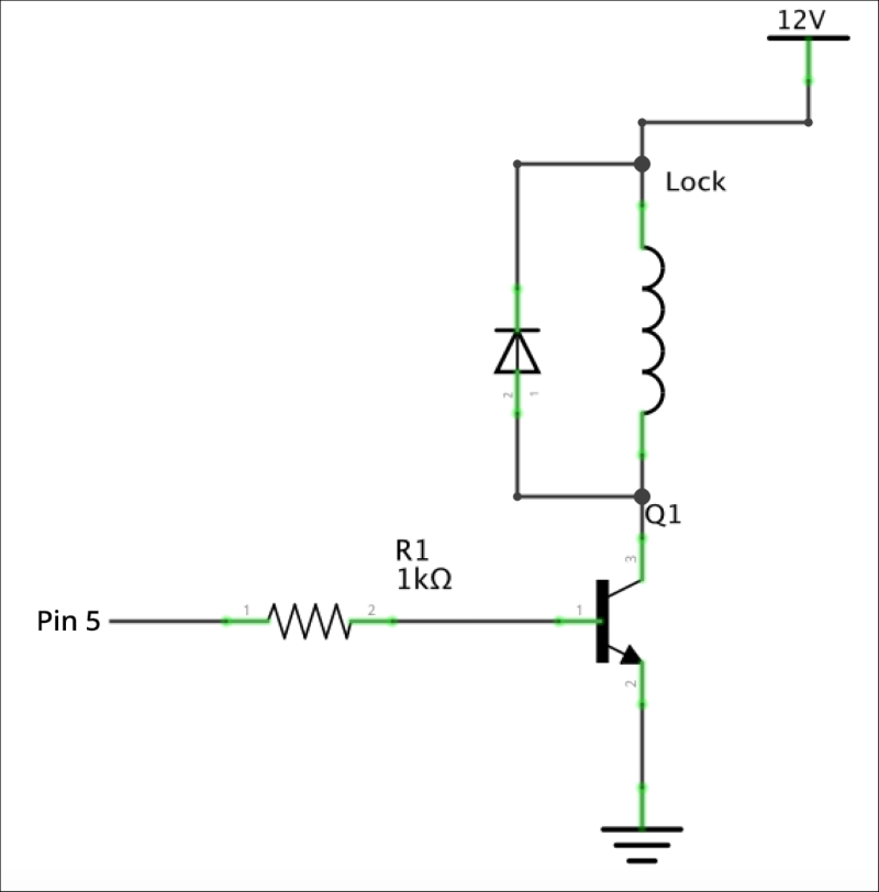
This schematic represents how you should connect the lock to the ESP8266. First, place the transistor on the breadboard, and connect the base of the transistor to the ESP8266 via the 1K Ohm resistor. Then, connect the emitter of the transistor to the ground of the ESP8266. After that, connect the door lock to the 12V DC power supply and to the remaining pin of the transistor. Finally, connect the diode in parallel to the lock, as indicated on the schematics. Note that ...
Get Internet of Things with ESP8266 now with the O’Reilly learning platform.
O’Reilly members experience books, live events, courses curated by job role, and more from O’Reilly and nearly 200 top publishers.

