5 Lateral Vehicle Dynamics and Control
5.1 General Equations of Lateral Vehicle Dynamics[1–2]
In motion, vehicles modeled as a rigid body have six degrees of freedom. In this chapter, vehicles are assumed to only have planar motion parallel to the road’s surface. But, considering the tyre cornering properties, we assume the following:
- No vertical, pitch, or roll motion with respect to the y-axis and x-axis, respectively
- For constant speed motion, no account is taken of the tangential force and aerodynamic effect
- Ignoring the influence of the clearance, friction and deformation of the steering system, and taking the rotation angle of the front wheel as an input directly
- The change of the tyre characteristics and the role of the aligning torque on the left wheel caused by load changes are disregarded.
Then, the vehicle is simplified as a “bicycle” model, as shown in Figure 5.1, which is the two degrees of freedom model with lateral and yaw motion.
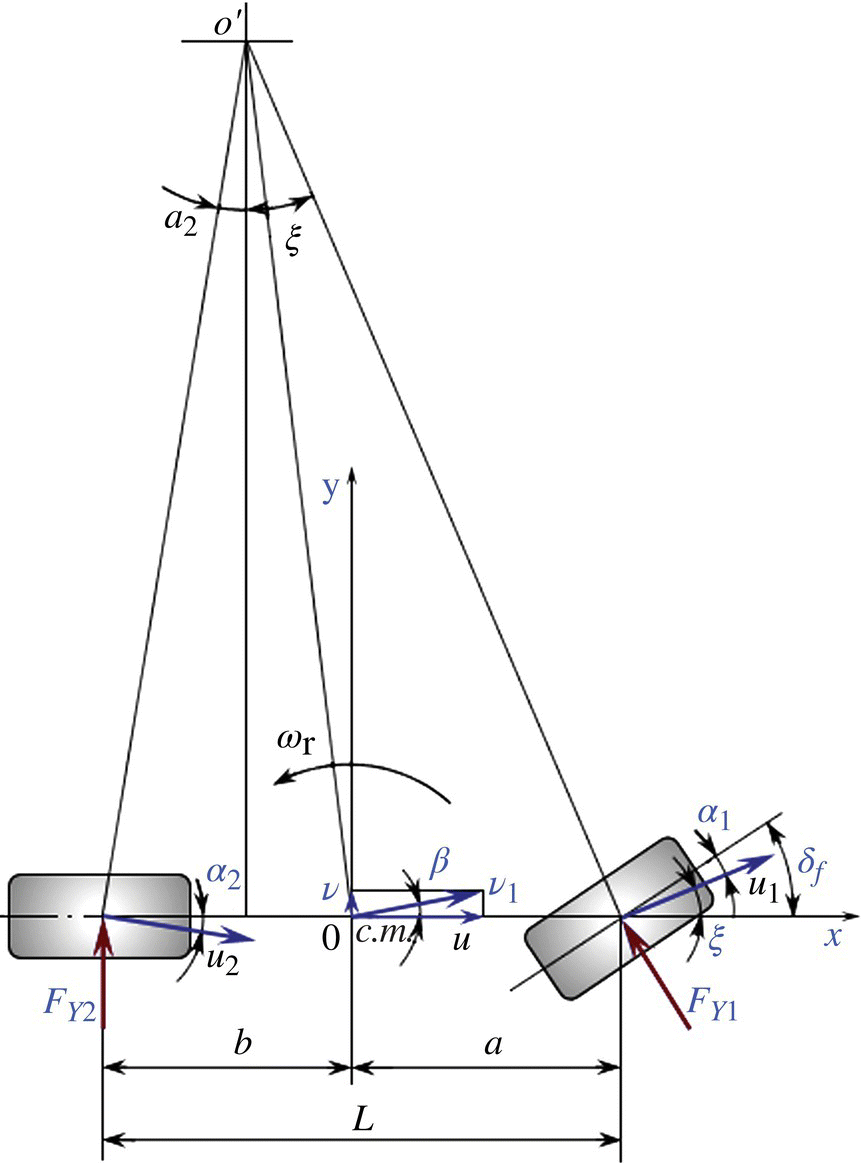
Figure 5.1 Two degrees of freedom vehicle model.
The vehicle receives the driver’s instructions, the front wheel is turned by an angle δf , the centrifugal force is generated at the centroid, which causes lateral reaction forces Fy1 and Fy2 on the front and rear, and the corresponding cornering angles α1 and α2, respectively. Thus, the direction of the front and rear wheel speeds u1 and u2 can be determined. According to the ...
Get Integrated Vehicle Dynamics and Control now with the O’Reilly learning platform.
O’Reilly members experience books, live events, courses curated by job role, and more from O’Reilly and nearly 200 top publishers.

