Receiver Logic Functions
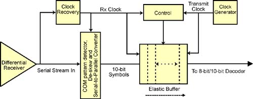
Figure 26-24 on page 728 illustrates the receiver logic's front end. This is comprised of:
The differential receiver.
The clock recovery logic.
The COM character detector.
Lane-to-lane de-skew logic.
Deserializer.
Figure 26-24. Receiver Logic's Front End
Differential Receiver
Refer to Figure 26-4 on page 686. The differential receiver on each lane senses voltage differences > 175mV:
+ difference = logical 1.
– difference = logical 0.
A signal difference < 85mV is considered a signal absent condition. During this time, the receiver de-gates its input to prevent the error circuit from detecting an error.
When a device's Physical ...
Get InfiniBand Network Architecture now with the O’Reilly learning platform.
O’Reilly members experience books, live events, courses curated by job role, and more from O’Reilly and nearly 200 top publishers.

