120 Implementing IBM System Networking 10Gb Ethernet Switches
VLANs
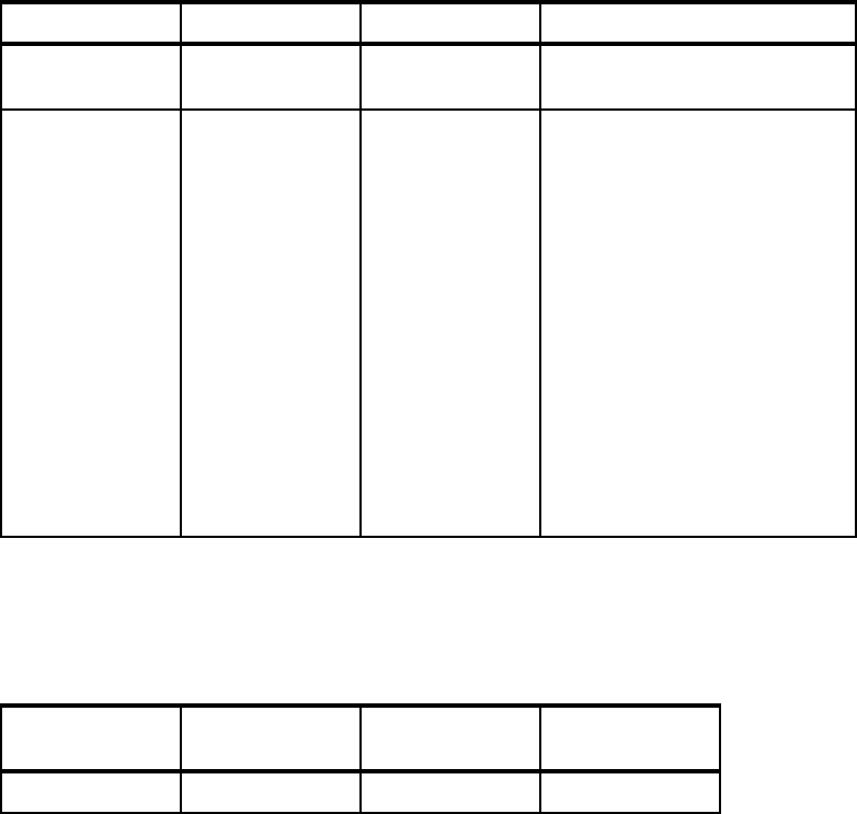
Table 3-13 shows VLANs used in the topology and the member ports of those VLANs.
Table 3-13 VLANs and port assignment
Spanning Tree Protocol
The STP mode that we use in our topology is Per-VLAN Rapid Spanning Tree Protocol
(PVRSTP). Table 3-14 shows the STP priorities for our different VLANs.
Table 3-14 STP bridge priorities
Port1:14 and port2:14 on access switches (ACC-3-1 and ACC-3-2) are configured as Fast
Forward ports.
To prevent unwanted topology changes, caused by plugging another switch into topology,
configure BPDU Guard on all ports on ACC-3-1 and ACC-3-2 switches other than those ports
used in the topology.
3.3.3 Layer 3 architecture
This section describes the IPv4 and IPv6 addressing plan and the complete Layer 3
architecture that are part of both Top-of-Rack and BladeCenter implementations.
VLAN number VLAN name Description Member ports
VLAN4095 Mgmt VLAN Management
VLAN
ACC-3, port15 (MGT1)
ACC-3-2, port15 (MGT1)
VLAN30 Server 3 VLAN VLAN for Server
farm 3
ACC-3, port 1:14 (untagged)
ACC-3, port 1:17 (tagged)
ACC-3, port 1:18 (tagged)
ACC-3-2, port 2:14 (untagged)
ACC-3-2, port 2:17 (tagged)
ACC-3-2, port 2:18 (tagged)
AGG-1, port1 (tagged)
AGG-1, port5 (tagged)
AGG-1, port21 (tagged)
AGG-1, port22 (tagged)
AGG-2, port1 (tagged)
AGG-2, port5 (tagged)
AGG-2, port21 (tagged)
AGG-2, port22 (tagged)
VLAN (STG) Priority on
ACC-3
Priority on
AGG-1
Priority on
AGG-2
30 (30) Default (61470) 0 4096
Chapter 3. Reference architectures 121
IPv4 and IPv6 addressing
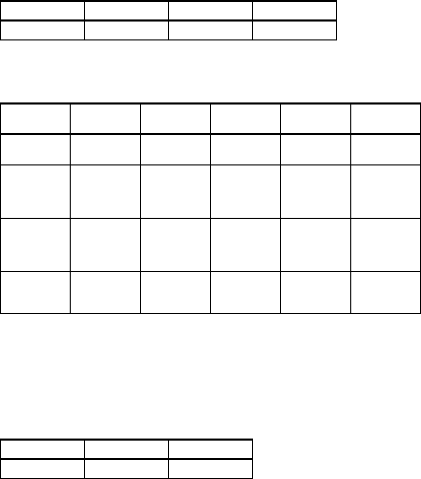
Table 3-15 shows the IPv4 and IPv6 address spaces assigned for VLAN 30.
Table 3-15 IP address ranges
Table 3-16 shows the IP addresses assigned to devices that have IP interfaces in VLAN30
and VLAN40.
Table 3-16 IPv4 and IPv6 addresses assignment
VRRP configuration
The communications within one VLAN is done by using the access layer switches.
Inter-VLAN communications is done by using aggregation layer switches (AGG-1, AGG2)
configured with VRRP groups for different VLANs.
The VRRP priorities should be kept in-line with STP bridge priorities, that is, the STP root
bridge should be the VRRP active router. Table 3-17 shows the VRRP priorities.
Table 3-17 VRRP groups and priorities
VLAN IPv4 IPv6 Description
30 10.0.30.0/24 FC30::0/64 VLAN30
VLAN IPv4
interface
IPv4 address IPv6
interface
IPv6 address Device
VLAN30 Bonding
interface
10.0.30.30 Bonding
interface
FC30::30/64 SRV-3
VLAN30 30 10.0.30.2 36 FC30::2/64
FC30::1/64
secondary
anycast
AGG-1
VLAN30 30 10.0.30.3 36 FC30::3/64
FC30::1/64
secondary
anycast
AGG-2
VLAN30 Virtual router
30
10.0.30.1 n/a n/a VRRP 30 on
AGG-1 /
AGG-2
VRRP group AGG-1 priority AGG-2 priority
30 105 100 (default)
Get Implementing IBM System Networking 10Gb Ethernet Switches now with the O’Reilly learning platform.
O’Reilly members experience books, live events, courses curated by job role, and more from O’Reilly and nearly 200 top publishers.

