Chapter 5. Sysplex functions 181
Can also be upgraded from
9674 R06 models
See Chapter 2, “zSeries 900 system structure” on page 17 for a description of SAPs, MBAs
and STIs.
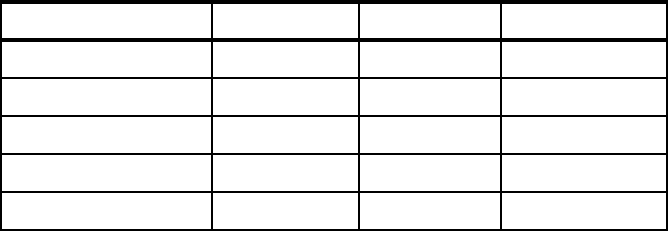
Table 5-2 lists the options for the standalone CF z900 Model 100.
Table 5-2 Coupling Facility (Model 100)
5.2.3 Operating system to CF connectivity
The connectivity from a z/OS and/or OS/390 image to a Coupling Facility (and vice-versa) is
provided by coupling channels (coupling links). z/OS and/or OS/390 images and CF images
may be running on the same or on separate servers. Every z/OS or OS/390 image in a
Parallel Sysplex must have at least one coupling link to each CF image.
For availability reasons, there should be:
At least two coupling links between z/OS and/or OS/390 and CF images
At least two CF images (not running on the same server)
At least two CF images are required for system-managed CF structure duplexing
At least one standalone CF (if running with just “Resource Sharing” only, then a
stand-alone CF is not mandatory)
5.2.4 ICF processor assignments
Model 100
The advantage of using ICFs instead of CPs for CF Images is that, because an ICF cannot
run any z/OS or OS/390 operating systems, software licenses are not charged for those
processors.
The z900 Model 100 cannot have CPs or Integrated Facility for Linux (IFL), so it is an ICF-only
machine to run CF Images. The ICFs can be dedicated, shared, or both.
Feature Minimum Maximum Increment
ICF
a
a. Two SAPs come with the Model 100 and anywhere from 1 to 9 spare PUs,
depending on the number of ICFs.
191
Memory
b
b. Increments are 6, 7, 8, 10, 12, 14, 16, 20, 24, 28, and 32 GB.
5 GB 32 GB (see note b)
ISC-3
(c
,
d)
c. ISC-3 runs in either Native or Compatibility mode. There are up to four
ISC-3 links per card. A link may be defined as Native or Compatibility.
Link definitions on the same card can be a mixture of modes.
d. There is a system minimum of 1 ICB-3
or
1 ISC-3 channel and a system
maximum of 64 coupling channels, which can be a combination of
ICB-3/ICB or ISC-3 channels.
042
e
e. Via RPQ 8P2248, otherwise 32.
1
ICB-3 Peer
(d)
0161
ICB Compatibility 0 16
f
f. Up to 16 is available via RPQ and on configurations with from 13-16 ICBs,
the compatibility I/O cage FC 2022
cannot be configured.
1
182 IBM eServer zSeries 900 Technical Guide
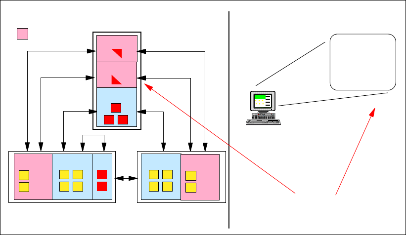
Figure 5-2 on page 182 shows an example of what logical processor assignments for the
z900 Model 100 would be defined in the partition image profile.
LP for CF 1 would have three dedicated ICF processors assigned.
LP for CF 2 would have one shared ICF processor assigned.
LP for CF 3 would have one shared ICF processor assigned.
This flexibility is very useful for mixed environments where a z900 Model 100 is being used for
more than one Parallel Sysplex system. Figure 5-2 also shows the z900 with an ICF partition
defined with two dedicated ICF processors.
Figure 5-2 Model 100 - ICF assignment example
A z900 Model 100 can have up to 15 Coupling Facility Images, each one having one of the
following:
Dedicated ICF processors
Shared ICFs
Dedicated and
Shared ICFs
General purpose models
Currently, the general purpose z900 models are the following models:
101 to 109
– 12 PU MCM (non-turbo)
1C1 to 1C9 (capacity models)
– 20 PU MCM (non-turbo)
110 to 116
– 20 PU MCM (non-turbo)
2C1 to 2C9 (capacity models)
– 20 PU MCM (turbo)
210 to 216
Function
Setup
HMC
z900
Partition
Image
Profiles
z/OS CF
CF (1)
CF (2)
CF (3)
z900 Model 100
Test Sysplex
z/OS z/OS z/OS
z900 z900
Get IBM eServer zSeries 900 Technical Guide now with the O’Reilly learning platform.
O’Reilly members experience books, live events, courses curated by job role, and more from O’Reilly and nearly 200 top publishers.

