42 IBM eServer zSeries 900 Technical Guide
Modular Cooling Unit
The Modular Cooling Units (MCUs) are the main components of the z900 servers’
refrigeration system. There are two MCUs mounted above the CPC to provide N+1 cooling for
the MCM. MCUs are made up of three subsystems:
The Modular Refrigeration Unit (MRU)
The Motor Scroll Assembly (MSA)
The Motor Drive Assembly (MDA)
In addition to the MCUs, the refrigeration subsystem has an evaporator, a dry air subsystem,
and board heater cartridges, all located on the CPC cage.
The MCUs utilize a closed-loop liquid cooling subsystem and incorporate an N+1 design
point, enabling concurrent maintenance. One MCU may be serviced concurrently while the
system is running. MCU sensors detect the installation site’s air temperature and humidity
and adjust the server interior environment accordingly.
There are two MCU types, one for the 12-PU MCM servers, and another for the 20-PU MCM
servers. Both non-turbo and turbo 20-PU MCMs use the same MCU type. Upgrades from a
12-PU MCM to any 20-PU MCM z900 model require that the MCUs be replaced.
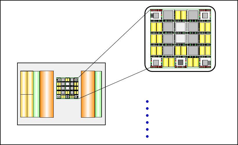
2.4.7 MultiChip Module design
The z900 MultiChip Module (MCM) is the world’s densest logic package (Figure 2-9). The
20-PU MCM contains 35 chips (30 are CMOS 8SE technology on turbo models or CMOS 8S
technology on non-turbo models) and the 12-PU MCM has 23 chips (18 are CMOS 8S). This
127 x 127 mm ceramic substrate consists of 101 layers of glass ceramic and 6 layers of thin
film wired with 1 km of wire. It has more than 2.5 billion transistors, copper interconnects and
4224 pins.
Figure 2-9 MultiChip Module
CPC Cage - front view
M
E
M
O
R
Y
0
M
E
M
O
R
Y
3
C
A
P
/
S
T
I
C
A
P
/
S
T
I
S
T
I
S
T
I
S
T
I
S
T
I
MBA
SD5
4 MB
SD1
4 MB
SD7
4 MB
SD3
4 MB
SD6
4 MB
SD2
4 MB
SD4
4 MB
SD0
4 MB
MBA
MBA MBA
SC1
SC0
CL K
PU2 PU3
PU6
PU4
PU7
PU5
PUB PU1
PUA PU0
PU1 2 PU13 PU9 PU8
PUC PUD
PU10
PUE
PU1 1
PUF
MultiChip Module (MCM)
(127 x 127 mm)
35 chips on 20-PU MCMs
23 chips on 12-PU MCM
2.5 billion transistors
101 glass ceramic layers
6 thin film layers
4224 pins
MBA
SD5
4 MB
SD1
4 MB
SD7
4 MB
SD3
4 MB
SD6
4 MB
SD2
4 MB
SD4
4 MB
SD0
4 MB
MBA
MBA MBA
SC1
SC0
CLK
PU2 PU3
PU6
PU4
PU7
PU5
PUB PU1
PUA PU0
PU12 PU13 PU9 PU8
PUC PUD
PU10
PUE
PU11
PUF
Chapter 2. zSeries 900 system structure 43
The MCM includes up to 20 PUs, the System Controller Element (SCE), four Memory Bus
Adapters (MBAs), and the system clock. The 20-PU SCE’s Cache Level 2 (L2) size is 32 MB
and consists of 234 million transistors incorporated in a binodal design.
The Cryptographic Coprocessor chips, called Cryptographic Elements (CEs), are not
mounted on the MCM. They are designed as Single-Chip Modules (SCMs) mounted on the
rear CPC cage and individually serviceable. This eliminates the need for changing the MCM
in the event of a CE chip failure.
The MCM plugs into a board that in turn is part of the CPC cage. All z900 MCMs are cooled
by IBM’s Modular Cooling Units (MCUs).
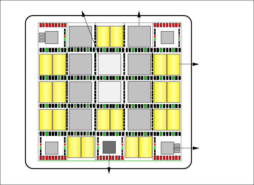
Figure 2-10 shows the 20-PU MCM and its 35 chips:
20 PU CMOS 8S chips on non-turbo models
20 PU CMOS 8SE chips on turbo models
2 Storage Control (SC) CMOS 8S chips
8 Storage Data (SD) CMOS 8S chips (4 MB each)
4 Memory Bus Adapter (MBA) chips
1 Clock chip
Figure 2-10 20-PU MultiChip Module
MBA
SD5
4 MB
SD1
4 MB
SD7
4 MB
SD3
4 MB
SD6
4 MB
SD2
4 MB
SD4
4 MB
SD0
4 MB
MBA
MBA MBA
SC1
SC0
CLK
PU2 PU3
PU6
PU4
PU7
PU5
PUB PU1
PUA PU0
PU12 PU13 PU9 PU8
PUC PUD
PU10
PUE
PU11
PUF
Processing Unit
Chip
Storage Control Chip
Storage Data Chip
Memory Bus
Adapter Chip
Clock Chip
Get IBM eServer zSeries 900 Technical Guide now with the O’Reilly learning platform.
O’Reilly members experience books, live events, courses curated by job role, and more from O’Reilly and nearly 200 top publishers.

