44 IBM CSM to IBM Systems Director Transformation Guide
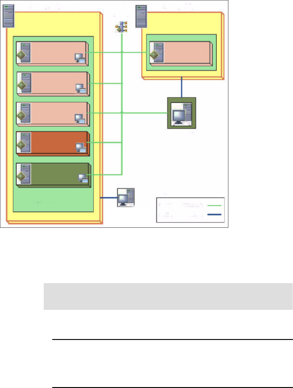
Figure 3-2 CSM environment for the coexistence scenario
3.2.2 Cluster verification
Before starting the transformation, it is important to perform functional verification to ensure
your cluster is working correctly.
List the nodes that are managed by CSM, as shown in Example 3-1.
Example 3-1 List the CSM-managed nodes
p5570lp01(root)/> lsnode
p5570lp02
p5570lp03
p5570lp04
p6lp01
p5570lp01(root)/>
Managed System
Managed System
Power 5
Power 6
HMC1 - CSM
Hardware Control
Point
CSM Cluster
HMC2 - CSM
Hardware Device
Virtual Server: p61p01
OS: AIX 6.1 TL 06 SP 05
Role: CSM client
Virtual Server: p55701p04
OS: AIX 6.1 TL6 SP5
Role: CSM note
Virtual Server: p55701p03
OS: AIX 6.1 TL 06 SP 05
Role: CSM note
Virtual Server: p55701p02
OS: AIX 5.3 TL 12 SP 01
Role: CSM note
Virtual Server: p55701p01
OS: AIX 6.1 TL 06 SP 01
Role: CSM & NIM Srv
Virtual Server: p5570vio1
VIOS 2.2.0.11-FP-24 SP-01
Role: CSM HW Device
CSM Logical Network
HMC Logical Network
Note: CSM executable commands can be found in the /opt/csm/bin directory. That
directory is in the PATH in the following examples, as typically recommended during CSM
implementation. Therefore, full path names are not used.

Chapter 3. Transformation scenarios 45
The 3 nodes p5570lp02, p5570lp03, p5570lp04 are the POWER5 LPARs and node p6lp01
is the POWER6 LPAR.
List the hardware devices that are managed by CSM as shown in Example 3-2.
Example 3-2 List all the CSM-managed hardware devices
p5570lp01(root)/> lshwdev
hmc2
p5570vio1
p5570lp01(root)/>
The HMC that manages the POWER6 server is hmc2 and p5570vio1 is the VIO Server for
the POWER5 server.
The node group CSM1_nodegroup contains all the CSM-managed nodes. See
Example 3-3.
Example 3-3 Show the members of the CSM node group
p5570lp01(root)/> nodegrp CSM1_nodegroup
p5570lp02
p5570lp03
p5570lp04
p6lp01
p5570lp01(root)/>
The csmstat command displays the status of each node, as shown in Example 3-4.
Example 3-4 Show the status of the CSM-managed nodes
p5570lp01(root)/> csmstat
---------------------------------------------------------------------------------
Hostname HWControlPoint Status PowerStatus Network-Interfaces
---------------------------------------------------------------------------------
p5570lp02 hmc1 on on en0-Online en1-Online
p5570lp03 hmc1 on on en0-Online en1-Online
p5570lp04 hmc1 on on en0-Online
p6lp01 hmc2 on on en0-Online
p5570lp01(root)/>
In many CSM environments, customer utilize the distributed condition-response
capabilities. We have created a condition and a response to demonstrate this.
The condition Filesystem_Tmp_Monitor1 is defined for the node p5570lp02. This condition
sends an email to the root user when the /tmp file system utilization exceeds 90%. The
condition gets rearmed when the percentage utilization drops below 75%. Refer to
Example 3-5.
Example 3-5 List the details of the distributed RMC condition
p5570lp01(root)/> lscondition Filesystem_Tmp_Monitor1
Displaying condition information:
condition 1:
Name = "Filesystem_Tmp_Monitor1"
Node = "p5570lp01"
MonitorStatus = "Monitored"
ResourceClass = "IBM.FileSystem"
EventExpression = "PercentTotUsed>90"
Get IBM CSM to IBM Systems Director Transformation Guide now with the O’Reilly learning platform.
O’Reilly members experience books, live events, courses curated by job role, and more from O’Reilly and nearly 200 top publishers.

