Flow Control Buffer Arrangement
Figure 5-3 on page 107 illustrates the general arrangement of HyperTransport flow control buffers and counters required of each link receiver interface. Note that while the transmit interface maintains flow control counters, the flow control buffers are only on the receive side of each device.
Figure 5-3. Flow Control Buffers And Counters
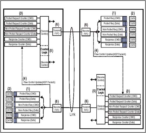
Details Associated With Figure 5-3
The following section describes the architectural features shown in Figure 5-3 on page 107. Note that the drawing is conceptual and is intended to show the major features of flow control on a single link. For multiple-link devices such as tunnels, ...
Get HyperTransport™ System Architecture now with the O’Reilly learning platform.
O’Reilly members experience books, live events, courses curated by job role, and more from O’Reilly and nearly 200 top publishers.

