9.7 Estimation Problems in the Drive with Filters
9.7.1 Introduction
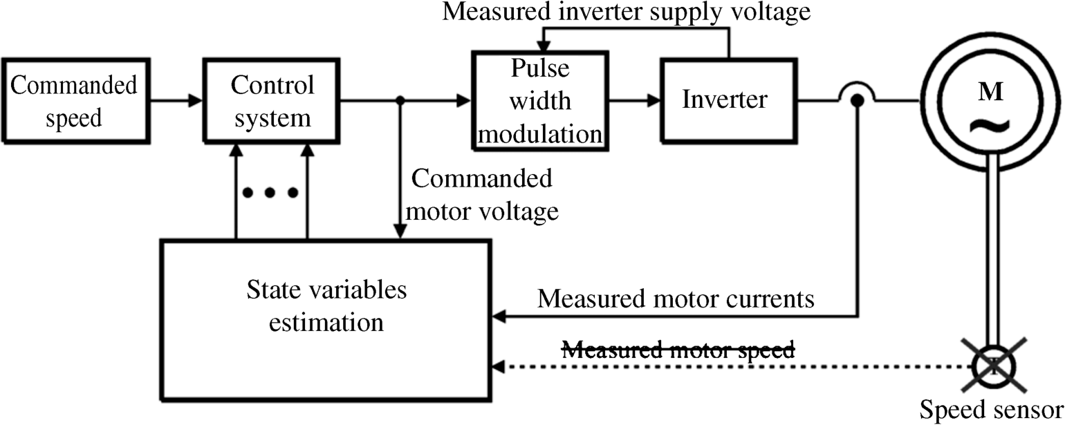
For motor closed loop control purposes, the actual controlled state variables have to be known. In most control systems, the controlled variables are mechanical speed, magnetic flux, and motor torque. The speed is easy to measure; however, measuring other variables is not so simple. In spite of the easy speed measurement in modern drives, the requirements for speed sensor elimination exists. To solve these problems, numerous estimation methods are used and the variables are calculated on-line. Then the sensors are limited to only the current and voltage sensors installed inside the converter. To prevent noise, all sensors should be installed inside the converter box. A drive with such limited sensors is known as a sensorless drive. The general structure of the sensorless AC drive is presented in Figure 9.50.
Figure 9.50 General structure of the sensorless AC drive

In the literature, numerous sensorless solutions are proposed. A comprehensive review can be found in [20]. But most of the solutions presented are applicable for the drives without motor filter use.
In the case of motor filter use, the estimation process is more complicated. Some of the solutions propose the installation of voltage and current sensors outside the converter for direct motor current and voltage measurement [21,22]. Unfortunately, as was ...
Get High Performance Control of AC Drives with Matlab / Simulink Models now with the O’Reilly learning platform.
O’Reilly members experience books, live events, courses curated by job role, and more from O’Reilly and nearly 200 top publishers.

