3.8 Quasi Impedance Source or qZSI Inverter
The impedance source or Z-source inverter, described in Section (7) suffers from the drawback of discontinuous input (DC) current during boost mode, high voltages across the capacitors, and higher stress on power switches. These shortcomings are overcome by a different topology of inverter called qZSI [58–61]. The qZSI topology is derived from the original Z-source inverter. The advantages of a qZSI are:
- draws continuous current from DC source;
- the voltage across the capacitor C2 is reduced;
- lower component count and hence higher reliability and higher efficiency; and
- lower voltage stress on the power switches.
There are several topologies of qZSI reported in the literature 59. This section elaborates on the voltage fed qZSI with continuous input current, as shown in Figure 3.75. The two operating modes of the inverter are the shoot-through and non-shoot-through modes, and the equivalent circuits during the modes of operation are shown in Figure 3.75. From the circuit (Figure 3.76a), the voltage relations during the non-shoot-through period (Tnsh) are
Figure 3.76 Equivalent circuit of the qZSI; a non-shoot-through state, b. shoot-through state
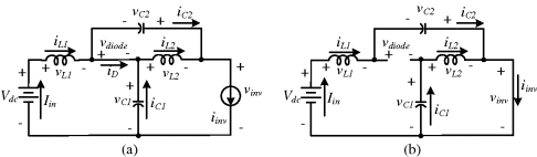
From the circuit (Figure 3.76b), the voltage relations during the shoot-through ...
Get High Performance Control of AC Drives with Matlab / Simulink Models now with the O’Reilly learning platform.
O’Reilly members experience books, live events, courses curated by job role, and more from O’Reilly and nearly 200 top publishers.

