163
Chapter 8, How to Hack a Building-Size Display
Project Demo
After you’ve set up the system you’ve decided to build, carefully apply
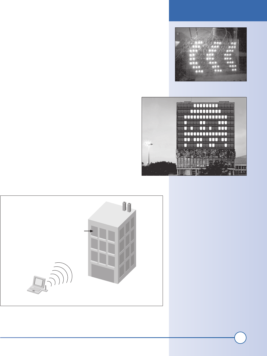
power and load one of the Blinkenlights movies. You can see a desktop
system running in Figure 8-25.
And, as Figure 8-26 shows, having a whole building lit up with animated
movies can be very impressive.
Wireless Extensions
One of the most time-consuming tasks when setting up a large
building is running the wires to each lamp. With some addi-
tional hacking, it is possible to use low-cost wireless links to
eliminate the thousands of meters of wire.
A single transmitter attached to the control PC can broadcast
one frame of data 25 times per second. Each receiver has a
unique address and looks for its state (either on or off) for that
frame of data. At the end of the transmission, all of the receiv-
ers make their state change. Each receiver needs a strong signal
from the transmitter connected to the control PC. An easy way
to accomplish this is to place the control PC and transmitter in
front of the building windows at street level, therefore ensuring
line of sight to each receiver. An overview of this idea is shown
in Figure 8-27.
Figure 8-25: Desktop system LEDs
Figure 8-26: Large-scale system in action
Channel Coder/Decoder
A company called RadioTronix has
a nice application note on channel
coding (http://www.radiotronix.com/
an401.pdf). It outlines a simple and
effective method for encoding data
for a radio channel.
Building
Window light with receiver
Control PC with transmitter
Figure 8-27: Wireless system overview
Wireless Extensions
ch08_building.indd 163
1/21/2002 1:03:00 PM

164
Part II: Advanced Hacks, Tools, and Techniques
Each lamp (or set of lamps) must be outfitted with an addressable radio
receiver. Several companies sell low-cost radio receivers that can be used for
this purpose. Figure 8-28 shows a block diagram of a wireless lamp control-
ler, and Figure 8-29 shows a block diagram for a simple transmitter.
The radio link provided by the inexpensive receivers will require additional
software to allow for reliable data transmission and reception. Figure 8-30
shows the different operations that the data must undergo in order to be
reliably transmitted over a “raw” radio link. There are many other methods
available, but this one is simple and reliable.
In order to receive a radio channel coded packet, the inverse of the transmit
operations must be performed. This chain of functions is shown in Figure
8-31.
Error Control Coder
The radio channel will likely have
noise on it from time to time. To
prevent noise from hindering reliable
data reception, an error-correcting
code should be applied to all data.
You’ll find a good explanation of
error correcting codes at http://www.
eccpage.com/. The web page also
includes C source code. For this sim-
ple system, I recommend a BCH code.
Each frame should be organized into
a packet and a few command codes
defined.
Error coder
Data input (data
payload, address,
desired function)
Packetizer Channel coder Radio hardware
Figure 8-30: Wireless transmitter software
Radio hardware
Data output (data
payload, address,
desired function)
Channel decoder Depacketizer
Error code
decoder
Figure 8-31: Wireless receiver software
Micro-
controller
Low-cost
radio
receiver
Relay
Relay driver
transistor
120V socket
120V plug
Lamp
Figure 8-28: Wireless lamp receiver
RS-232
interface
From PC Serial port
Low-cost
radio
transmitter
Figure 8-29: Wireless transmitter
Wireless Extensions
ch08_building.indd 164
1/21/2002 1:03:07 PM
Get Hardware Hacking Projects for Geeks now with the O’Reilly learning platform.
O’Reilly members experience books, live events, courses curated by job role, and more from O’Reilly and nearly 200 top publishers.

