104
Part I: Basic Hacks, Tools, and Techniques
Project Overview
When I began this hack, I looked at a number of inexpensive color video
cameras. One of the first I experimented with was the X-10 wired color
video camera, which has been advertised extensively on the Web.
I purchased one of these cameras and connected it to see the image quality
it produced. After connecting the camera to a small LCD television, I was
immediately disappointed with the results. The images had little color and
would often break up if the lighting levels changed even slightly. It was clear
that I needed a better solution.
A quick search in the DigiKey catalog yielded the answer: a small color
video camera made by Panasonic. After a quick test of image quality, this
camera looked right for the project.
You will assemble this camera and mounting hardware in a few simple
steps. The camera will be connected to a small LCD monitor that you will
install inside the car for viewing the video images. The camera will be pro-
tected inside of a Pactec plastic case.
Hardware Assembly Instructions
For this project, you will need to know how to solder and how to read a
schematic diagram.
1. Assemble the camera housing
To begin, you will need the Pactec plastic
housing, the Panasonic color video camera,
two 2-56 screws (1 inch long) and nuts, and
a small piece of clear Lucite. You will be
drilling and cutting holes in the plastic case
to hold the camera and protect it from the
elements.
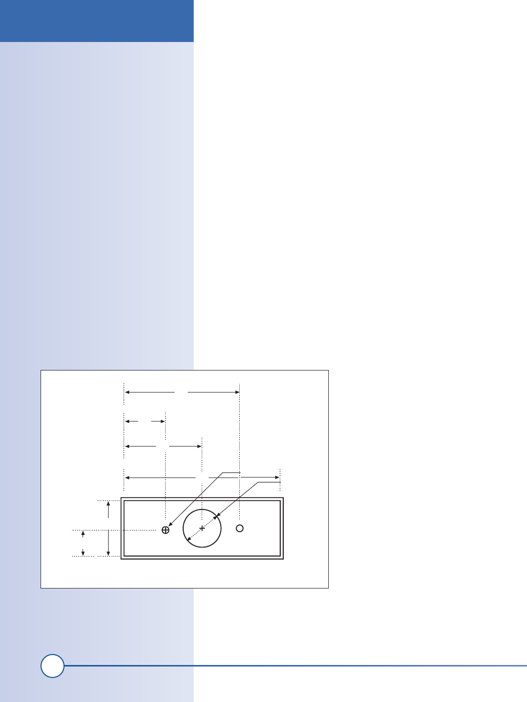
Drill holes in front of the plastic enclosure
You will need to make several holes for the
camera lens and mounting points on one
side of the Pactec housing, as shown in
Figure 6-1. Note that the measurements are
in inches. If you use a different housing, you
will need to adjust these measurements.
1.54
All measurements made from inner ‘lip’ of component
0.56
1.05
2.10
ø
0.10
ø
0.50
0.76
0.35
Figure 6-1: Camera cutouts
Project Overview
ch06_periscope.indd 104
1/21/2002 12:48:28 PM
105
Chapter 6, How to Hack a Video Periscope for Your Car
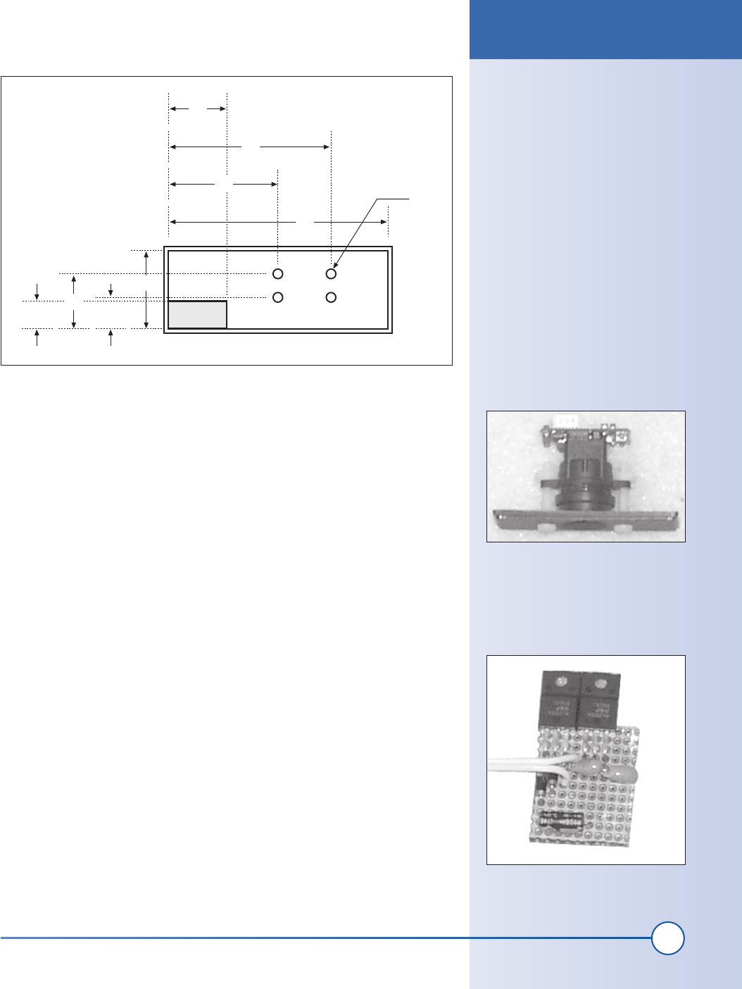
Cut exit hole for wire
Next, cut several holes in the back of the plastic enclosure to allow the
video and power cables to exit. You will also need to cut holes that allow
you to capture the cables inside the enclosure with tie wraps. Cut holes in
the pattern shown in Figure 6-2. You do not need to be exact about these
dimensions.
Mount the camera
The Panasonic camera has two holes on either side of the lens. These holes
will easily fit a 2-56 threaded screw. Use two 1-inch-long, nylon 2-56 screws
to hold the camera to the front plate you cut in the previous task. You can
see what this looks like in Figure 6-3. Do not tighten the screws too much,
as you will later need to adjust the focus of the camera by rotating the front
lens on the camera.
2. Assemble the power supply
The camera requires a 5V power supply to operate, and the LCD TV set I
used requires just over 6 volts. The cigarette lighter socket in your car sup-
plies 12 volts, and the circuit converts it to the required 5 and 6 volts. You
can easily build this circuit in about an hour.
Build the simple power supply according to the schematic diagram in
Exhibit B. This circuit can be built in a small piece of perforated board and
placed inside a small insulating enclosure. When you are done, it should
look similar to what you see in Figure 6-4.
Figure 6-3: Camera mount
1.30
All measurements made from inner ‘lip’ of component
0.40
0.90
2.10
ø
0.10
0.76
0.50
0.20
0.25
Figure 6-2: Camera enclosure back diagram
Figure 6-4: Power supply PCB
Hardware Assembly Instructions
ch06_periscope.indd 105
1/21/2002 12:48:30 PM
Get Hardware Hacking Projects for Geeks now with the O’Reilly learning platform.
O’Reilly members experience books, live events, courses curated by job role, and more from O’Reilly and nearly 200 top publishers.

