3
Introduction
Wire. I keep several spools of wire (30-gauge stranded,
24-gauge stranded, solid-core 20-gauge stranded,
16-gauge stranded, and multi-conductor ribbon
cable) on hand. It will make your work go faster if
you have these readily available.
Hot-melt glue gun. Hot-melt glue is amazing stuff—it’s
nearly flawless at causing any two solid items to stick
together. It is as useful as duct tape and used almost
as often by electronics hackers. I have an inexpensive
“no-name” brand gun; any brand will do the trick.
These are the basic tools you will want to have on hand
for most of the simpler hacks I cover in this book. Part
II, Advanced Hacks, Tools, and Techniques will cover
the kinds of skills you’ll need to tackle the more compli-
cated hacks. Each hack in this book requires only a small
subset of the tools described here, but if you’re going to
call yourself a tinkerer and invent your own hacks, you’ll
want to be acquainted with all the tools in this toolbox.
The Basics
Hacking hardware usually involves several basic activi-
ties: reading schematic drawings that describe circuits, connecting elec-
tronic components using solder, and measuring signals in electronic cir-
cuits using a multi-meter. Before you jump into the first few projects in this
book, you need to know how to perform these activities.
How to read a schematic diagram
The schematic diagram is a standard method for describing how to connect
the various parts in an electrical circuit. It shows all of the components
used, their values and important part details, and how they connect to the
other components. A symbol and a label represent each component.
The circuits in most of the hacking projects in this book will be described
using schematic diagrams. Knowing how to read a schematic diagram will
also allow you to design and build your own hacking projects.
Schematic diagrams can look complex, but once you know the basic rules
of how they are drawn they will be easy to decipher. I will cover the basics
of schematic diagram reading in the next few paragraphs, referring back to
the example diagram in Figure I-2. Being able to read these diagrams will
increase the number of projects you can tackle.
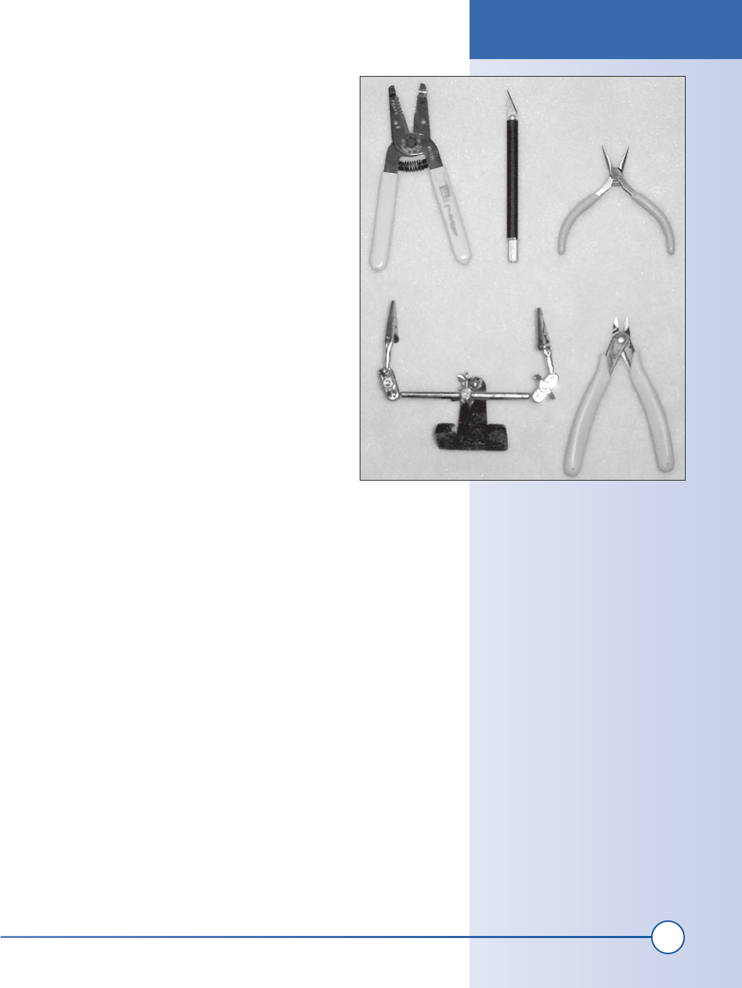
Figure I-1: Hand tools (clockwise from
top left are wire strippers, printer’s knife,
needlenose pliers, wire cutters, and
helping hands)
The Basics
part1.indd 3
1/13/2002 2:51:13 PM
4
Part I: Basic Hacks, Tools, and Techniques
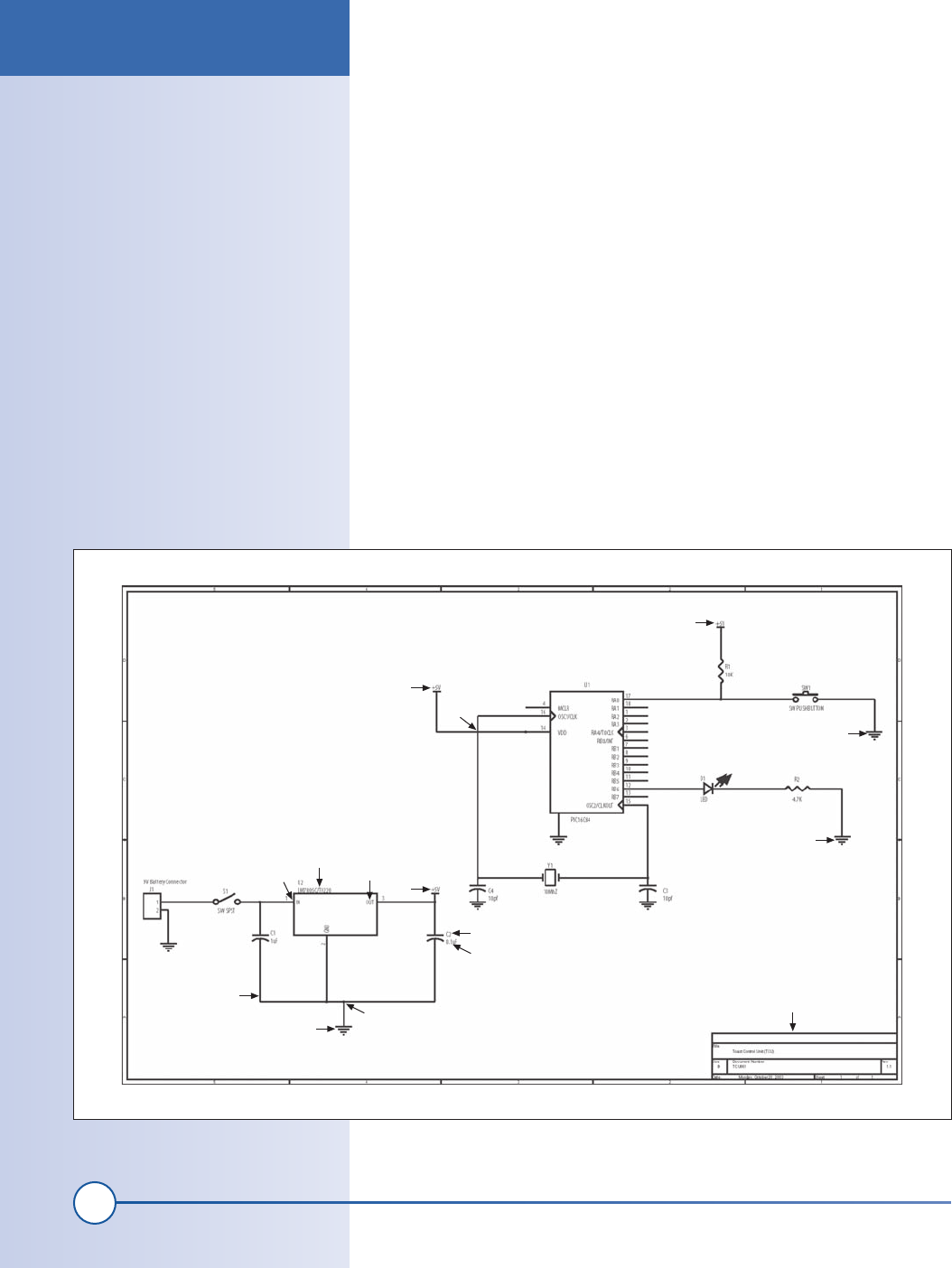
Let’s begin by looking at a simple schematic diagram and talking about the
meaning of each marking. Figure I-2 shows a typical schematic diagram.
Many components of a schematic diagram have a border with letters and
numbers along each edge to make it easier to communicate the location of a
part. There is usually a title block that describes when the diagram was cre-
ated and by whom, a brief description, and a revision number. You can see
a title block at location 8 in our example. Each electronic part is represented
by a symbol of some sort. The symbols vary from simple boxes to more
complex drawings. In our example, location 1 shows a voltage regulator. It
is represented by a box with an identification called a part reference, shown
at 2 as U2, with three lines coming out of it, each with a number next to
it. The number shown at 3 is one of the wires, also known as pins, which
protrude from the component. The line shown at 4 represents a wire that
connects the bottom pin of C2, a capacitor, and point 6, 5, and the bottom
pin of C1. The dot at 6 represents a point where three wires are connected.
Note that when two lines representing electrical connections cross over
each other in a schematic diagram, it does not mean they are connected. At
point 10 in the example, two lines representing electrical connections cross,
but because there is no dot at the intersection, they are not connected.
Dots and Lines in
Schematic Diagrams
Are you lost yet? Think of the sche-
matic diagram as a roadmap. The
electronic components are the build-
ings and the wires are the roads.
When two roads cross without a dot,
think of that point as an overpass.
When the lines cross with a dot, it is
an intersection. Each building has a
name, represented by the identifica-
tion letter/number scheme.
C
D
E
A
B
F
B
A
G
G
J
G
E
E
H
Figure I-2: Example schematic diagram
The Basics
part1.indd 4
1/13/2002 2:51:16 PM
Get Hardware Hacking Projects for Geeks now with the O’Reilly learning platform.
O’Reilly members experience books, live events, courses curated by job role, and more from O’Reilly and nearly 200 top publishers.

