Appendix D. Reading Schematic Diagrams
So far, we have used very detailed illustrations to describe how to assemble our circuits, but as you can imagine, it's not exactly a quick task to draw one of those for any experiment you want to document.
Similar issues arise, sooner or later, in every discipline. In music, after you write a nice song, you need to write it down using musical notation.
Engineers, being practical people, have developed a quick way to capture the essence of a circuit in order to be able to document it and later rebuild it or pass it to somebody else.
In electronics, schematic diagrams allow you to describe your circuit in a way that is understood by the rest of the community. Individual components are represented by symbols that are a sort of abstraction of either the shape of the component or the essence of them. For example, the capacitor is made of two metal plates separated by either air or plastic; therefore, its symbol is:

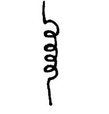
Another clear example is the inductor, which is built by winding copper wire around a cylindrical shape; consequently the symbol is:
The connections between components are usually made using either wires or tracks on the printed circuit board and are represented on the diagram as simple lines. When two wires are connected, the connection ...
Get Getting Started with Arduino now with the O’Reilly learning platform.
O’Reilly members experience books, live events, courses curated by job role, and more from O’Reilly and nearly 200 top publishers.

