Output Stages and Power Amplifiers
The amplifier circuits studied in previous chapters aim to achieve a high gain with desirable input and output impedance levels. However, many applications require circuits that can deliver a high power to the load. For example, the cellphone described in Chapter 1 must drive the antenna with 1 W of power. As another example, typical stereo systems deliver tens or hundreds of watts of audio power to speakers. Such circuits are called “power amplifiers” (PAs).
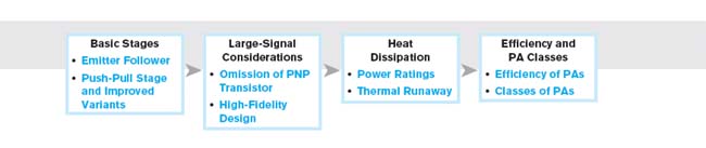
This chapter deals with circuits that can provide a high output power. We first reexamine circuits studied in previous chapters to understand their shortcomings for this task. Next, we introduce the “push-pull” stage and various modifications to improve its performance. The chapter outline is shown below.
14.1 GENERAL CONSIDERATIONS
The reader may wonder why the amplifier stages studied in previous chapters are not suited to high-power applications. Suppose we wish to deliver 1 W to an 8-Ω speaker. Approximating the signal with a sinusoid of peak amplitude VP, we express the power absorbed by the speaker as
![]()
where denotes the root mean square (rms) value of the sinusoid and RL represents ...
Get Fundamentals of Microelectronics, 2nd Edition now with the O’Reilly learning platform.
O’Reilly members experience books, live events, courses curated by job role, and more from O’Reilly and nearly 200 top publishers.

