i
i
i
i
i
i
i
i
13
More Ray Tracing
A ray tracer is a great substrate on which to build all kinds of advanced rendering
effects. Many effects that take significant work to fit into the object-order ras-
terization framework, including basics like the shadows and reflections already
presented in Chapter 4, are simple and elegant in a ray tracer. In this chapter we
discuss some fancier techniques that can be used to ray-trace a wider variety of
scenes and to include a wider variety of effects. Some extensions allow more gen-
eral geometry: instancing and constructive solid geometry (CSG) are two ways
to make models more complex with minimal complexity added to the program.
Other extensions add to the range of materials we can handle: refraction through
transparent materials, like glass and water, and glossy reflections on a variety of
surfaces are essential for realism in many scenes.
This chapter also discusses the general framework of distribution ray trac-
ing (Cook et al., 1984), a powerful extension to the basic ray-tracing idea in which
multiple random rays are sent through each pixel in an image to produce images
with smooth edges and to simply and elegantly (if slowly) produce a wide range
of effects from soft shadows to camera depth-of-field.
If you start with a brute-
force ray intersection loop,
you’ll have ample time to
implement an acceleration
structure while you wait for
images to render.
The price of the elegance of ray tracing is exacted in terms of computer time:
most of these extensions will trace a very large number of rays for any non-trivial
scene. Because of this, it’s crucial to use the methods described in Chapter 12 to
accelerate the tracing of rays.
303
i
i
i
i
i
i
i
i
304 13. More Ray Tracing
13.1 Transparency and Refraction
In Chapter 4 we discussed the use of recursive ray tracing to compute specular,
or mirror, reflection from surfaces. Another type of specular object is a dielec-
tric—a transparent material that refracts light. Diamonds, glass, water, and air are
dielectrics. Dielectrics also filter light; some glass filters out more red and blue
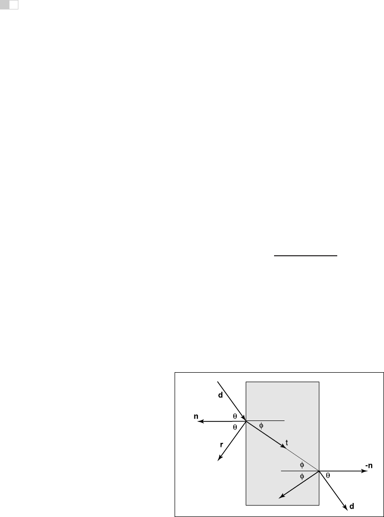
light than green light, so the glass takes on a green tint. When a ray travels from
a medium with refractive index n into one with a refractive index n
t
, some of the
light is transmitted, and it bends. This is shown for n
t
>nin Figure 13.1. Snell’s
law tells us that
n sin θ = n
t
sin φ.
Computing the sine of an angle between two vectors is usually not as convenient
Example values of
n
:
air: 1.00;
water: 1.33–1.34;
window glass: 1.51;
optical glass: 1.49–1.92;
diamond: 2.42.
as computing the cosine, which is a simple dot product for the unit vectors such
as we have here. Using the trigonometric identity sin
2
θ +cos
2
θ =1, we can
derive a refraction relationship for cosines:
cos
2
φ =1−
n
2
1 − cos
2
θ
n
2
t
.
Note that if n and n
t
are reversed, then so are θ and φ as shown on the right of
Figure 13.1.
To convert sin φ and cos φ into a 3D vector, we can set up a 2D orthonormal
basis in the plane of the surface normal, n, and the ray direction, d.
From Figure 13.2, we can see that n and b form an orthonormal basis for the
plane of refraction. By definition, we can describe the direction of the transformed
Figure 13.1. Snell’s Law describes how the angle φ depends on the angle θ and the
refractive indices of the object and the surrounding medium.
Get Fundamentals of Computer Graphics, 3rd Edition now with the O’Reilly learning platform.
O’Reilly members experience books, live events, courses curated by job role, and more from O’Reilly and nearly 200 top publishers.

