
i
i
i
i
i
i
i
i
8
The Graphics Pipeline
The previous several chapters have established the mathematical scaffolding we
need to look at the second major approach to rendering: drawing objects one by
one onto the screen, or object-order rendering. Unlike in ray tracing, where we
consider each pixel in turn and find the objects that influence its color, we’ll now
instead consider each geometric object in turn and find the pixels that it could have
an effect on. The process of finding all the pixels in an image that are occupied by
Any graphics system has
one or more types of “prim-
itive object” that it can han-
dle directly, and more com-
plex objects are converted
into these “primitives.” Tri-
angles are the most often
used primitive.
a geometric primitive is called rasterization, so object-order rendering can also
be called rendering by rasterization. The sequence of operations that is required,
Rasterization-based sys-
tems are also called
scanline renderers
.
starting with objects and ending by updating pixels in the image, is known as the
graphics pipeline.
Object-order rendering has enjoyed great success because of its efficiency.
For large scenes, management of data access patterns is crucial to performance,
and making a single pass over the scene visiting each bit of geometry once has
significant advantages over repeatedly searching the scene to retrieve the objects
required to shade each pixel.
The title of this chapter suggests that there is only one way to do object-
order rendering. Of course this isn’t true—two quite different examples of graph-
ics pipelines with very different goals are the hardware pipelines used to sup-
port interactive rendering via APIs like OpenGL and Direct3D and the software
pipelines used in film production, supporting APIs like RenderMan. Hardware
pipelines must run fast enough to react in real time for games, visualizations,
and user interfaces. Production pipelines must render the highest quality anima-
tion and visual effects possible and scale to enormous scenes, but may take much
161
i
i
i
i
i
i
i
i
162 8. The Graphics Pipeline
more time to do so. Despite the different design decisions resulting from these
divergent goals, a remarkable amount is shared among most, if not all, pipelines,
and this chapter attempts to focus on these common fundamentals, erring on the
side of following the hardware pipelines more closely.
The work that needs to be done in object-order rendering can be organized
into the task of rasterization itself, the operations that are done to geometry be-
fore rasterization, and the operations that are done to pixels after rasterization.
The most common geometric operation is applying matrix transformations, as
discussed in the previous two chapters, to map the points that define the geometry
from object space to screen space, so that the input to the rasterizer is expressed
in pixel coordinates, or screen space. The most common pixelwise operation is
hidden surface removal which arranges for surfaces closer to the viewer to appear
in front of surfaces farther from the viewer. Many other operations also can be in-
cluded at each stage, thereby achieving a wide range of different rendering effects
using the same general process.
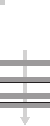
For the purposes of this chapter we’ll discuss the graphics pipeline in terms of
four stages (Figure 8.1). Geometric objects are fed into the pipeline from an inter-
DISPLAY
BLENDING
FRAMEBUFFER IMAGE
FRAGMENTS
TRANSFORMED GEOMETRY
COMMAND STREAM
FRAGMENT PROCESSING
RASTERIZATION
VERTEX PROCESSING
APPLICATION
Figure 8.1. The stages of
a graphics pipeline.
active application or from a scene description file, and they are always described
by sets of vertices. The vertices are operated on in the vertex-processing stage,
then the primitives using those vertices are sent to the rasterization stage.The
rasterizer breaks each primitive into a number of fragments, one for each pixel
covered by the primitive. The fragments are processed in the fragment processing
stage, and then the various fragments corresponding to each pixel are combined
in the fragment blending stage.
We’ll begin by discussing rasterization, then illustrate the purpose of the geo-
metric and pixel-wise stages by a series of examples.
8.1 Rasterization
Rasterization is the central operation in object-order graphics, and the rasterizer
is central to any graphics pipeline. For each primitive that comes in, the rasterizer
has two jobs: it enumerates the pixels that are covered by the primitive and it
interpolates values, called attributes, across the primitive—the purpose for these
attributes will be clear with later examples. The output of the rasterizer is a set of
fragments, one for each pixel covered by the primitive. Each fragment “lives” at
a particular pixel and carries its own set of attribute values.
In this chapter, we will present rasterization with a view toward using it to
render three-dimensionalscenes. The same rasterization methods are used to draw
Get Fundamentals of Computer Graphics, 3rd Edition now with the O’Reilly learning platform.
O’Reilly members experience books, live events, courses curated by job role, and more from O’Reilly and nearly 200 top publishers.

