
i
i
i
i
i
i
i
i
7
Viewing
In the previous chapter we saw how to use matrix transformations as a tool for
arranging geometric objects in 2D or 3D space. A second important use of geo-
metric transformations is in moving objects between their 3D locations and their
positions in a 2D view of the 3D world. This 3D to 2D mapping is called a viewing
transformation, and it plays an important role in object-order rendering, in which
we need to rapidly find the image-space location of each object in the scene.
When we studied ray tracing in Chapter 4, we covered the different types of
perspective and orthographic views and how to generate viewing rays according
to any given view. This chapter is about the inverse of that process. Here we
explain how to use matrix transformations to express any parallel or perspective
view. The transformations in this chapter project 3D points in the scene (world
space) to 2D points in the image (image space), and they will project any point on
a given pixel’s viewing ray back to that pixel’s position in image space.
If you have not looked at it recently, it is advisable to review the discussion of
perspective and ray generation in Chapter 4 before reading this chapter.
By itself, the ability to project points from the world to the image is only
good for producing wireframe renderings—renderings in which only the edges
of objects are drawn, and closer surfaces do not occlude more distant surfaces
(Figure 7.1). Just as a ray tracer needs to find the closest surface intersection
along each viewing ray, an object-order renderer displaying solid-looking objects
has to work out which of the (possibly many) surfaces drawn at any given point
on the screen is closest and display only that one. In this chapter, we assume we
are drawing a model consisting only of 3D line segments that are specified by
141
i
i
i
i
i
i
i
i
142 7. Viewing
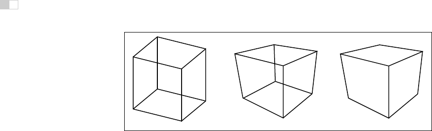
Figure 7.1. Left: wireframe cube in orthographic projection. Middle: wireframe cube in
perspective projection. Right: perspective projection with hidden lines removed.
the (x, y, z) coordinates of their two end points. Later chapters will discuss the
machinery needed to produce renderings of solid surfaces.
7.1 Viewing Transformations
The viewing transformation has the job of mapping 3D locations, represented
as (x, y, z) coordinates in the canonical coordinate system, to coordinates in the
image, expressed in units of pixels. It is a complicated beast that depends on
Some APIs use “viewing
transformation” for just the
piece of our viewing trans-
formation that we call the
camera transformation.
many different things, including the camera position and orientation, the type
of projection, the field of view, and the resolution of the image. As with all
complicated transformations it is best approached by breaking it up in to a product
of several simpler transformations. Most graphics systems do this by using a
sequence of three transformations:
• A camera transformation or eye transformation, which is a rigid body trans-
formation that places the camera at the origin in a convenient orientation.
It depends only on the position and orientation, or pose, of the camera.
• A projection transformation, which projects points from camera space so
that all visible points fall in the range −1 to 1 in x and y. It depends only
on the type of projection desired.
• A viewport transformation or windowing transformation, which maps this
unit image rectangle to the desired rectangle in pixel coordinates. It de-
pends only on the size and position of the output image.
To make it easy to describe the stages of the process (Figure 7.2), we give names
to the coordinate systems that are the inputs and output of these transformations.
The camera transformation converts points in canonical coordinates (or world
Get Fundamentals of Computer Graphics, 3rd Edition now with the O’Reilly learning platform.
O’Reilly members experience books, live events, courses curated by job role, and more from O’Reilly and nearly 200 top publishers.

