Appendix BSquare‐Wave Frequency Spectrum
B.1 Introduction
One of the most powerful tools in circuit analysis is the Fourier analysis. Signals that enter a circuit are often repetitive but not sinusoidal. Typical repetitive signals are square waves, triangle waves, trapezoids, or pulses. Square waves can have different leading and falling edges. A Fourier analysis provides an infinite series of sine waves with different amplitudes that when added together create the original waveform. The response to a repetitive waveform is found by summing the responses to all the individual sine waves (harmonics). In most practical applications, the response to the first three harmonics is sufficient to characterize the amplitude of the waveform. The assumption that must be made is that the circuit being analyzed is linear. This means that the system does not generate new harmonics.
B.2 Ideal Square Waves
Figure B.1 shows how an ideal square wave voltage is built up from sinusoids. If the square wave were shifted in time by 90 electrical degrees, the harmonics would all be cosines.
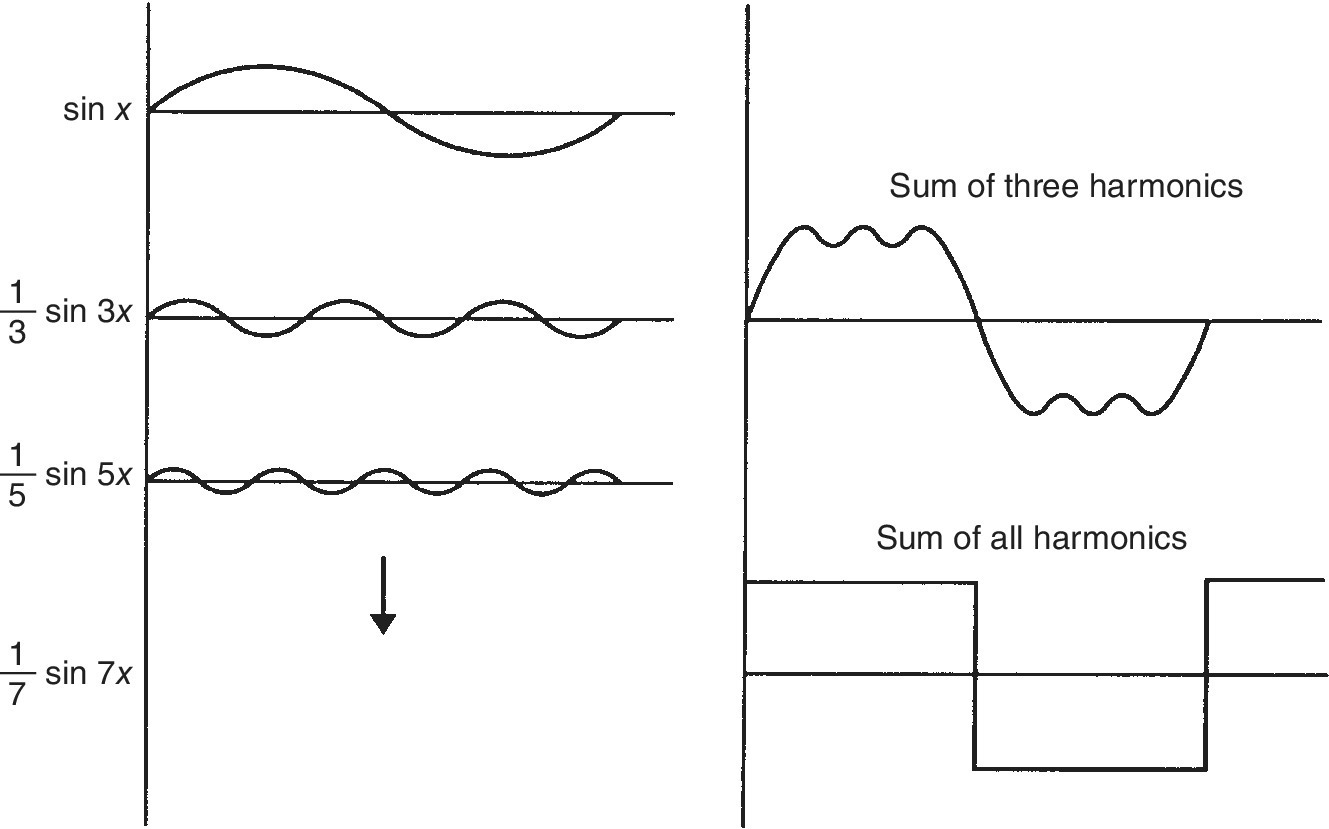
Figure B.1 The harmonics that make up a square wave.
The graphs that follow show the nature of the spectrum for square waves. Practical logic signals are not fully repetitive, so the harmonic content shown in the figures is approximate. Note that the amplitude A is one‐half the peak‐to‐peak value. For 5‐V logic, ...
Get Fast Circuit Boards now with the O’Reilly learning platform.
O’Reilly members experience books, live events, courses curated by job role, and more from O’Reilly and nearly 200 top publishers.

