Chapter 4. Bridging with Ethernet VPN
The first few chapters of this book provided the background and framework for Ethernet VPN (EVPN).
EVPN’s primary function is to support virtual Layer 2 (L2) network overlays. Bridging is how packet forwarding works in L2 networks. Therefore, in this chapter our focus is on how bridging works in EVPN networks. This study includes understanding control-plane and data-plane semantics associated with bridging. The details include a study of choices when it comes to handling frames destined to multiple Network Virtualization Edges (NVEs), handling Media Access Control (MAC) movement, and L2 loops. We study how EVPN works with multiattached endpoints such as dual-attached servers, a common deployment model with EVPN. We conclude with a study of Address Resolution Protocol (ARP) suppression and the benefits it provides.
An Overview of Traditional Bridging
To understand how bridging works with EVPN, we begin with a quick study of how bridging works in a traditional 802.1Q bridge. IEEE 802.1Q defined the standard that describes how VLAN-aware bridges work, and so traditional bridging is also called 802.1Q bridging or plain .1Q bridging. We also introduce the terminology commonly used in bridging. We then use this as the basis to describe how EVPN solves the same problem, albeit differently. A compare-and-contrast table at the end helps solidify these concepts further.
For the sake of this discussion, let us assume the network shown in Figure 4-1. The figure shows a simple Clos network with two spine switches labeled S1 and S2 and four leaf switches labeled L1 through L4. Hosts (or endpoints) A through F are attached to the leaves. There are two virtual networks, red and blue. In an 802.1Q bridge, these virtual networks will be VLANs. To simplify the mappings a reader has to maintain, we’ll refer to the MAC address of A as MACA. Similarly, we’ll assume that L1 connects to host A on PortA.
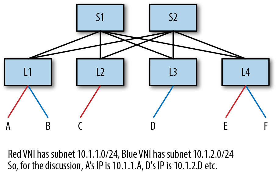
Figure 4-1. Sample topology
An 802.1Q bridge forwards a packet based on the VLAN and the destination MAC address of the packet. If a packet is received without a VLAN tag, the bridge port has a default VLAN tag associated with it. 802.1Q bridges use what is called “flood-and-learn” to populate the MAC forwarding table. What this means is that whenever a bridge receives a packet whose combination of VLAN and destination MAC address is not in the MAC forwarding table, the bridge sends the packet out every port that is in the same VLAN as the incoming packet. This is called flooding. However, the bridge filters out the ingress port from this list of ports the packet is flooded to. This filtering is called self-forwarding check. The other thing the bridge does is record the (VLAN, source MAC address) in the MAC forwarding table as being reachable on the ingress port. This is called learning. So, in Figure 4-1, when node L1 receives a packet from A destined to E, and it does not have an entry for (red VLAN, MACE) in its MAC forwarding table, it floods the packet out all ports which belong to the red VLAN. It filters out PortA from this list of ports. It also records that (red VLAN, MACA) is reachable via PortA in its MAC forwarding table.
This is done by every node in the packet’s path as it inexorably moves from the source to the destination. Thus, spines are not relieved from any duties when it comes to packet forwarding and knowledge of virtual networks. Hence, VLAN is not an overlay network virtualization technology.
How does a bridge know which ports belong to a specific VLAN? By configuration. In Figure 4-1, all the links between the leaves and spine switches carry both the red and blue VLAN traffic. Such links are called trunked links.
A careful reader trying to map this logic with a packet trace in the topology of Figure 4-1 will realize that it is possible for a packet to loop in the network because of loops in the topology (consider the path L1–S1–L2–S2–L1, for example). To avoid this, a control protocol called the Spanning Tree Protocol (STP) is used to convert any topology into a loop-free topology by removing all redundant paths to a node. In other words, STP eliminates multipathing in a network.
Overview of Bridging with EVPN
Let us now reexamine bridging, but with EVPN. We will use the same communication example as in the previous section: host A wishes to correspond with host E. We will use Figure 4-1.
A few things to note to kick off the discussion. Packet forwarding between the leaves and spines happens via routing. For the sake of this discussion, assume that the control protocol used to set up the IP forwarding tables is BGP. This means all paths between the routers are used (i.e., multipathing works). Next, there are no VLANs on the links between the leaves and spine switches. We’re using VXLAN as the network virtualization overlay protocol. Network virtualization begins at the leaves. Therefore, the leaves are the network virtualization edges (NVEs) (i.e., they encapsulate and decapsulate VXLAN packets). As NVEs, they need to have tunnel addresses—IP addresses that are used in the VXLAN tunnel header. We’ll designate these addresses using the symbol VTEP: that is, L1’s tunnel IP address is VTEPL1, L4’s is VTEPL4, and so on. The VTEP IP address is typically the address assigned to the loopback device of the node. We will also enable 802.1Q traditional learning, but only on the edge ports. In Figure 4-1, the edge ports are all the end host facing ports. Now, let us begin.
To enable EVPN, we must first enable the Address Family Indicator (AFI)/Subsequent Address Family Indicator (SAFI) of EVPN, which is l2vpn/evpn in all the BGP peerings between the leaves and switches. We also enable the advertisement of information associated with each NVE’s locally attached virtual networks (see Chapter 6 for specific configuration commands).
Each NVE first advertises the list of all its locally attached virtual networks. In the case of L1, these are the red and blue virtual networks, for L2 it is only the red network, and so on. At the end of this advertisement exchange, all NVEs know what virtual networks are of interest to all the other NVEs in the network. The MAC forwarding tables are empty, so there are no MAC addresses to advertise at this point. Figure 4-2 illustrates this exchange from the point of view of L1. In fact, all EVPN packet exchanges follow this same model. A leaf sends information to its BGP peers, which are the spines, and the spines send information to their peers, the leaves.
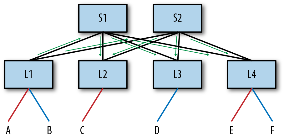
Figure 4-2. Illustrating a sample exchange of EVPN packet flow from the perspective of L1
Now A sends its packet to L1 destined to E. Figure 4-3 illustrates this packet flow.
-
The packet sent from A to L1 is no different in this case from traditional bridging. L1 receives this packet and, just as in traditional bridging, learns that MACA is reachable via PortA. Now, because L1 does not have any information about MACE, it decides to flood the packet, just as in traditional bridging. Remember, S1 and S2 know nothing about virtual networks because this is a network virtualization overlay solution. So, for L1 to flood the packet, it must encapsulate the packet in a VXLAN tunnel header and send the packet to the NVEs that have expressed an interest in the red virtual network. There are two main options for how this can be done. We discuss those in “Handling BUM Packets”.
-
For now, let’s just assume that L1 sends VXLAN-encapsulated packets to L2 and L4 (L3 does not have a red virtual network). L1 computes the hash on the packet header fields of the original packet and sets this to be the UDP source port in the VXLAN tunnel header. The packets are then routed to L2 and L4. In Figure 4-3, the packet to L2 is routed via S2, and the packet to L4 is routed via S1.
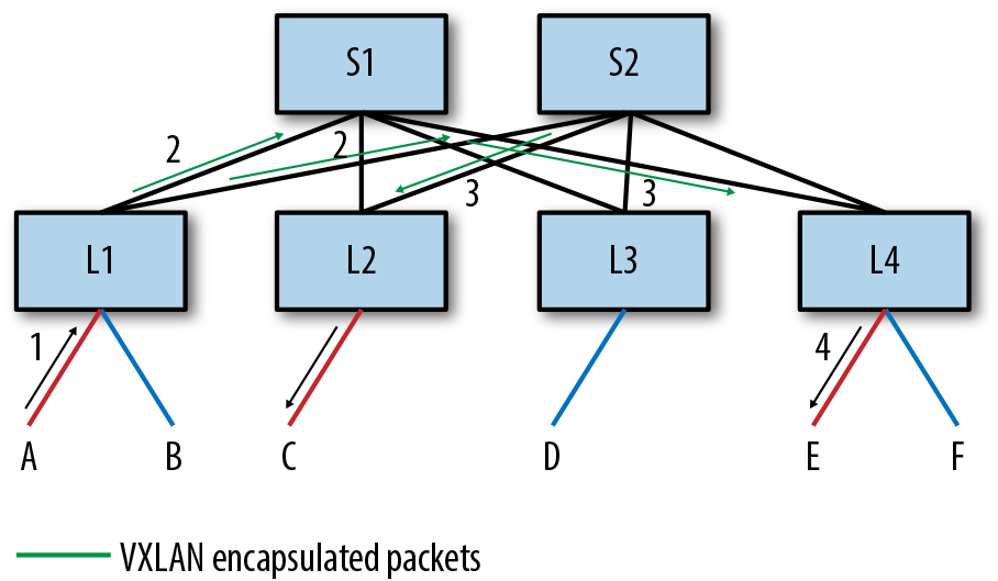
Figure 4-3. Flooding in an EVPN network, A → E
-
When these VXLAN-encapsulated packets reach L2 and L4, L2 and L4 each know that they are the end of the VXLAN tunnel because the destination IP address in the packet is their IP address and the User Datagram Protocol (UDP) destination port says that this is a VXLAN packet.
-
They decapsulate the packet and send the packet out of all the locally attached ports that are in the red virtual network. Neither L2 nor L4 attempt to send this packet in VXLAN-encapsulated form to any other node. Not flooding a VXLAN-encapsulated packet after decapsulation back into the VXLAN overlay is the equivalent of the self-forwarding check. In EVPN, it is referred to by its routing protocol name, split-horizon check.
Neither L2 nor L4 learn anything about MACA from this flooded packet. However, L1 has a new local entry in its MAC forwarding table. So L1 advertises the reachability to MACA in the red virtual network via a BGP EVPN message. Specifically, it uses a Route Type 2 (RT-2) message, which carries the {VNI, MAC} advertisement. The message says that MACA in the red virtual network is reachable via the VXLAN Tunnel End Point (VTEP) L1.1 L1 delivers this information to its BGP peers, S1 and S2. S1 and S2 in turn deliver this message to their peers, L2, L3, and L4. L2 and L4 populate their MAC forwarding tables with information about MACA. They note that MACA is remote and reachable via the VTEP L1. L3 which has no red VNI simply stores this message (or can discard it). We discuss why L3 even gets this message in “Why Does NVE L3 Get an Advertisement for MACA?”. This BGP exchange is as illustrated earlier in Figure 4-2.
Figure 4-4 shows the packet flow of E’s reply to A.
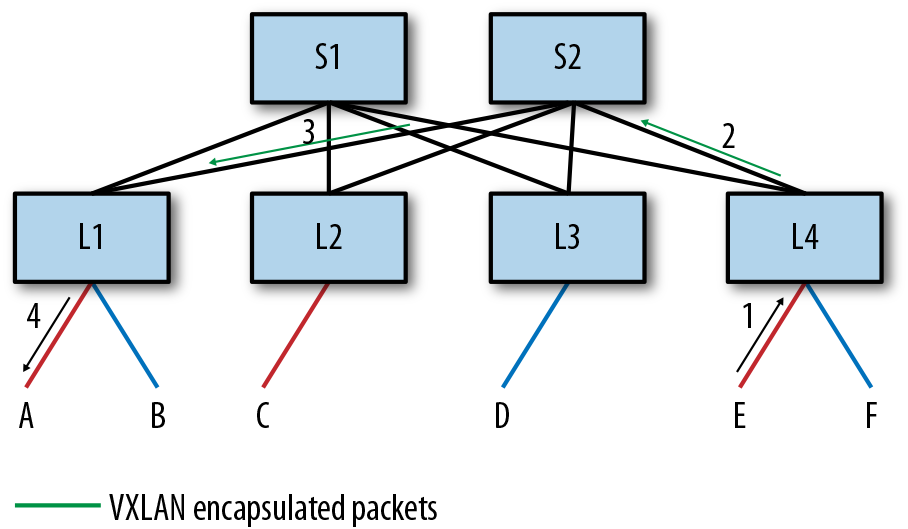
Figure 4-4. Packet flow from E to A with EVPN
-
E sets the destination MAC address of the packet to be MACA, and the source MAC to be MACE and sends the packet to L4. L4 receives this message on PortE. L4 learns this MAC address to port association because it is received on a locally attached port. L4 knows that MACA is a remote MAC reachable via VTEPL1 from the earlier EVPN message. It therefore VXLAN encapsulates the packet with the destination IP address of VTEPL1, and the source IP address of VTEPL4. It computes the hash on the packet header fields of the original packet and sets this to be the UDP source port in the VXLAN tunnel header. The packet is next routed to VTEPL1 via the usual IP routing rules.
-
Because L4 had learned via BGP that VTEPL1 is reachable via both S1 and S2, it uses the hash of the packet (computed from the VXLAN header or the original, a matter of implementation) to pick either S1 or S2 and sends the packet to it. Let’s assume it picks S2.2
-
S2, upon receiving this packet, routes it out PortL1. When L1 receives this packet, it sees that the destination IP address is itself and strips off the VXLAN header. It looks for the destination MAC address on the exposed inner packet, which is MACA in the red virtual network.
-
The output of this lookup in the MAC forwarding table is PortA, and so L1 forwards the packet out PortA.
-
Finally, L4 advertises the reachability to MACE in the red virtual network to its BGP peers, S1 and S2. S1 and S2 in turn send the advertisement to their other BGP peers, L2, L3, and L4. L2 and L4 install the MAC entry for MACE as associated with VTEPL4 in their MAC forwarding table (see “Why Does NVE L3 Get an Advertisement for MACA?”).
Figure 4-5 illustrates how the packet headers are added as the packet flows from E to A. Only relevant fields from the packet headers are shown; there are obviously a lot more fields in the IP and VXLAN headers.
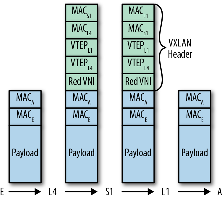
Figure 4-5. Packet headers in packet flow from E to A
Table 4-1 looks at how bridging works in both an 802.1Q bridge and an EVPN network.
| Behavior | 802.1Q Bridge | EVPN |
|---|---|---|
| Control protocol | STP | BGP EVPN |
| Knowing which edges are interested in a virtual network | No notion of remote edge; every hop along the way is aware of virtual network | Remote NVE interest in virtual network learned from BGP EVPN message |
| Behavior when destination is unknown | Flood along spanning tree, only on links carrying that virtual network | Flood to every VTEP interested in that virtual networka |
| Packet header carrying virtual network of the packet | 802.1q VLAN tag | VXLAN header |
| MAC to port association of local end host | .1Q bridge learning | .1Q bridge learning |
| MAC to port association of remote end host | .1Q bridge learning | BGP EVPN messages |
| All links in network utilized | No | Yes |
| Path from A → E versus the path from E → A | Same path used in forward and reverse paths | Different paths may be used in the forward and reverse paths |
a This is not entirely accurate, because there are choices. We study this in “Handling BUM Packets” | ||
What Ifs
In this section, we look at the behavior when a slightly different sequence of events happens, sequences that you might already be pondering.
What happens if the BGP advertisement about MACA didn’t get to L4 before the reply from E reaches L4? In this situation, L4 behaves just as L1 did: it sends the packet to all the NVEs interested in the red virtual network.
What happens to the packet from E if, upon reaching L1, it does not know where A is? Again, it behaves similarly to L4 in this case: it sends the packet out all locally attached ports in the red virtual network. In neither case (when the egress NVE is L1 or L4) does the packet ever get sent out a port with a VXLAN encapsulation due to the split-horizon check.
Why Does NVE L3 Get an Advertisement for MACA?
You might remember that the MAC advertisement about MACA and MACE was sent to L3, even though L3 had expressed no interest in the red virtual network. Why is that, and what does L3 do with this message?
This is an implementation detail, and it might be handled differently by various BGP implementations. Remember that the spine nodes, S1 and S2, are part of the underlay, and do not know anything about virtual networks. To ensure that L3 does not get the information, they would need to keep track of which BGP peers are interested in which virtual network. This is an unnecessary computation for them to perform. The implementation also scales much better if it does not need to keep track of virtual networks.
This implementation might have an additional benefit. If the red virtual network is attached to L3 at some point in the future, L3 is now interested in the red virtual network. If it already has the MAC advertisements for the red virtual network, packet flow between L2 and the other nodes can be much faster and result in less flooding. If L3 does not have the MAC advertisements, it must ask S1 and S2 to send it all the BGP EVPN updates again. It does this via a BGP Route Refresh message.3 This is somewhat inefficient. On the other hand, maintaining a copy of all MAC advertisements for networks in which it has no interest can cause bloated memory usage for a BGP process. In such a situation, it might be better to just drop the advertisement it receives rather than store it. At the time of this writing, FRR retains the MAC advertisements.
Handling BUM Packets
We were skimpy with the details on how flooding works in EVPN networks. You might also have noticed that two copies of the flood packet were sent, one to S1 and another to S2. How was this decided? We cover such details in this section.
The common terminology to refer to flooded packets is Broadcast, unknown Unicast, and unknown Multicast, or BUM, packets. EVPN provides two choices for packet forwarding of BUM packets: ingress replication and Layer 3 (L3) underlay multicast. In addition to this, some implementations might also provide the ability to drop all BUM packets. We discuss each in some more detail, including the trade-offs of each approach. This information helps administrators pick the right solution based on their enterprise needs instead of one dictated by the network vendor.
Ingress replication
In ingress replication, the ingress NVE sends multiple copies of a packet, one for each egress NVE interested in the virtual network. In our example, when A’s packet to E is flooded, L1 makes two copies—one for L2 and one for L4—and sends them off one by one.
The primary benefit of this model is that it keeps the underlay simple. The underlay needs to provide only IP unicast routing to support network virtualization. Furthermore, it is the simplest model to configure: there is no additional configuration required. The replication list is automatically built from the BGP EVPN RT-3 (carrying the Virtual Network Identifiers [VNIs] of interest to a VTEP) messages without any further intervention from the user. This makes the solution also more robust, because the chances of human error are reduced significantly.
The primary disadvantage of this approach is that the replication bandwidth required from the underlay can be high, especially if there are lots of BUM packets. If the number of NVEs to replicate to is no more than 64 to 128 nodes4 and the amount of BUM traffic is low, this approach works quite well. These two conditions are common enough that ingress replication is probably the most commonly deployed model for handling BUM packets in the data center. Even if the number of NVEs to replicate to is higher but the amount of traffic is low, this method works quite well. ARP suppression, which we discuss later in this chapter, helps reduce the most common source of BUM traffic.
L3 multicast support in the underlay network
The second approach to handling BUM packets is to use L3 multicast in the underlay network. By using multicast, the ingress NVE does not have to send a separate copy for each egress NVE. For the example described earlier, L1 would send a single copy to S1 and S1 would send multiple copies, one to each of the leaves. With just two egress NVEs in our example, the difference between the ingress replication and multicast approach is not apparent. If there were 20 egress NVEs in our example instead, L1 would send 20 copies to S1 (or divide that among S1 and S2, as described in the previous section). With L3 multicast, L1 would send a single copy or at most two copies (one each to S1 and S2), and they would replicate the packet to all the other relevant nodes.
The main advantage of this approach is that it is possible to handle a large volume of BUM packets or even well-known multicast packets efficiently. However, it is something of an administrative nightmare.
In this model, besides providing unicast routing support, the underlay must also provide multicast routing support. The most commonly used multicast routing protocol is called Protocol Independent Multicast (PIM). PIM is actually a family of protocols, providing for different ways to build a replication tree depending on the network topology and requirements. The most commonly deployed member of the PIM family is called PIM Sparse Mode (PIM-SM). However, the EVPN draft recommends using PIM Source-Specific Multicast (PIM-SSM) because it is more appropriate for this use case. Nonetheless, PIM-SSM is not commonly deployed in enterprise networks. On the other hand, PIM-SM requires additional protocols such as Session Discovery Protocol (SDP) for a reliable deployment. We do not have the space to get into explaining L3 multicast here. But deploying L3 multicast is sufficiently painful that everybody avoids it if possible.
Besides the complexity of enabling PIM and dealing with L3 multicast, this model has many other limitations. To ensure that for every virtual network only the associated NVEs get the packet, each virtual network must be in its own multicast group. But this would result in far too many multicast groups to scale well. So, the administrator must now manually map all of the virtual networks into a smaller number of multicast groups. This in turn leads to some NVEs receiving BUM packets for virtual networks in which they have no interest. Mapping a virtual network to a multicast group also adds significant configuration complexity. An administrator must configure the mapping of virtual network to multicast group on every single NVE. There is no simple way to ensure that this configuration is consistent and correct across all the NVEs.
Dropping BUM packets
BUM packets are considered by many network administrators to be a cheap way to launch a Distributed Denial-of-Service (DDoS) attack on the network. By sending packets to addresses that might never be seen by the network, less network bandwidth is available for legitimate traffic. Such packets can deluge end hosts in that virtual network and cause them to fail because the system is very busy coping with BUM packets.
Dropping BUM packets implies that after we hear from an endpoint, its MAC address is communicated to all the other nodes via BGP. Therefore, there is really no need to flood these packets. ARP/ND suppression, discussed later, also helps here.
If supported by an implementation, this option can be enabled. Some implementations allow for this to be enabled per virtual network or for all virtual networks.
The main disadvantage of this approach is possible communication breakdown with traffic meant for silent servers. For example, if E is a print server and is sitting idle, its MAC address is not known to L4 and so cannot be advertised. If A wants to send a print job to that printer, it cannot because L1 does not know where E is. But silent servers are increasingly rare, so this might not be a problem in networks anymore.
Signaling which approach is employed
Because there are choices, each NVE must inform the other NVEs of what it can support. RT-3 EVPN messages can carry a BGP attribute called Provider Multicast Service Interface (PMSI), which identifies the kind of BUM packet handling supported by this device. The PMSI attribute is defined in a completely different standard (RFC 6514) from the usual EVPN standards. The values suggested by the EVPN draft for signaling the replication model are:
3 for PIM-SSM
4 for PIM-SM
5 for PIM-BiDir5
6 for Ingress Replication
Unfortunately, dropping BUM packets is a local configuration knob, not advertised to other neighbors.
Handling MAC Moves
Now consider what happens if the endpoint named A moves from behind L1 to behind L2. This usually happens if A is a virtual machine (VM). Most endpoints send out an ARP message when they move. This ARP message is sent to the broadcast address and is an ARP reply packet. It is not a reply sent in response to any request. Hence, this message is called a Gratuitous ARP (GARP). If A sends a GARP in conjunction with its move to behind L2, L2 learns that MACA is local to it now. It must update its MAC forwarding table entry to have MACA point out its local port rather than it be associated with VTEPL1. Next, L2 must advertise its newly learned information to all the other VTEPs. It does so by sending a MAC advertisement via a BGP UPDATE (RT-2) message. When this update gets to L1, L1 faces a quandary. Its MAC forwarding table says MACA is a locally attached MAC. In regular BGP updates, BGP always prefers the local information to a host that is remote. How do we fix this?
EVPN defines a new BGP extended community called MAC Mobility to help with this. Figure 4-6 shows the format of this extended community.
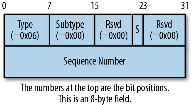
Figure 4-6. MAC Mobility extended community format
When L1 first advertised MACA in the red virtual network, MACA had not been advertised before. In such a situation, the advertisement is sent without tagging it with the MAC Mobility extended community. When L2 now wants to advertise about MACA, it tags the advertisement with the MAC Mobility extended community. The sequence number is set to 0. The presence of the MAC Mobility tag in the advertisement lets BGP prefer the remote advertisement over its local information. So L1 will update its MAC forwarding table entry as being behind VTEPL2. L1 will also withdraw its MAC advertisement for MACA.
If at a later time, A moves back behind L1 (or moves somewhere else, say behind L4), L1 to which it is now local will send out a new advertisement, but with an incremented sequence number. If BGP receives an update with a MAC Mobility tag with a sequence number greater than its local copy, it prefers the new update. If multiple updates are received for a MAC update with the same sequence number but with different VTEPs, the advertisement from the VTEP with the lowest VTEP IP address is selected.
If a MAC address is static6—that is, it is never supposed to move—the very first time the MAC address is advertised, it must be tagged with the MAC Mobility extended community with the “S” bit set to 1. When any VTEP receives a MAC advertisement with such a tag, it must ignore any locally detected changes in that MAC address in the associated virtual network.
Sometimes, messages indicating that a MAC address moved are incorrect. One reason is lax security in L2 networks, making it possible to spoof a MAC address and make it move from a safe host to a compromised host. Another reason for spurious moves is that a problem in a connected 802.1Q network can cause the STP to continuously update its tree. When the tree is updated, a MAC address might appear in a different location in the tree, making it look like the MAC address moved.
To handle all of these cases, if a VTEP detects that a MAC address is updating too frequently, it can stop sending or handling further updates to that MAC. It must also notify the administrator that this is happening. There is no clearly defined way to get out of this situation.
FRR’s EVPN implementation supports MAC Mobility as defined by the standard, with the caveat that it does not support any way to handle excessive MAC updates specially.
Support for Dual-Attached Hosts
In enterprise networks, compute nodes are frequently attached to more than one switch. This is primarily done to ensure that a single link failure or a single switch failure doesn’t leave a compute node disconnected from the network. This also allows upgrading of switches without taking down all the compute nodes associated with that switch during the upgrade window. As an enterprise network solution, EVPN is also frequently deployed with dual-attached hosts. We don’t discuss a variation of the same idea: multisite attachments where geographically disparate data centers are hooked up via some form of a Wide-Area Network (WAN) connection. The problems associated with such sites are more intricate.7
Figure 4-7 shows the network we’ve used all along, but with the hosts dual-attached to L1 and L2. I’ve come across deployments in which some nodes are dual-attached and some are single attached. This topology is not uncommon when the deployment is hosting multiple workloads, such as a modern Hadoop cluster and a more traditional application or even OpenStack.
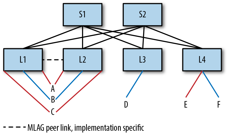
Figure 4-7. Dual-attached hosts in EVPN network
The following subsections address the problems of dual-connected hosts and how to address them. Following are the problems to be addressed:
How are the dual-attached hosts connected to the switches?
How is the dual-attached node seen by the other VTEPs? In other words, how do VTEPs L3 and L4 in Figure 4-7 view A, B, and C?
What happens when some of the hosts lose their connection to one of the switches? For example, what happens if C loses its link to L1?
How does packet delivery work for a multidestination frame, such as a BUM packet? Do A, B, and C get duplicates because L1 and L2 each deliver a copy? Duplicates can confuse certain applications if they’re not running over a reliable stream protocol such as TCP.
The Host-Switch Interconnect
In the most common deployment, the host treats the two links as being in a bond (aka link aggregation). The two main advantages of a bond are that both links are usable at the same time, and that as a bond, the link needs a single IP address instead of two. Using both links at the same time is also referred to as active–active mode. Creating a bond involves using a standard protocol called Link Aggregation Control Protocol (LACP). Using LACP ensures that the host is properly connected to the right devices. For example, if C accidentally hooks up a cable to L3 instead of L2, this is caught by LACP because C will discover that it is not communicating with the same entity on both the links. LACP supports bonding only if the links are connected to the same pair of devices on all links. LACP also catches problems such as unidirectional link failures. Some host vendors charge extra for enabling LACP, so many switch implementations support the notion of a static bond, in which the administrator configures the two ends of the link as being in a bond without using LACP.
Some customers use the dual-switch interconnect only to handle failure. In this case, one of the links is in standby mode. It comes alive only when the active link dies. This is called NIC teaming or active-standby mode. This mode makes some assumptions similar to the bond mode. It assumes that when the standby link comes alive, it has the same IP address as the recently deceased link. It also assumes that the default gateway is the same on this link as on the other link.
A third alternative is to treat each link as an independent link without LACP or bonding. In such a situation, the host can be made to use a single IP address, but this is a little more involved and is deployed in situations in which the host is either a router or a VTEP itself.
We’ll discuss the case in which the links are bonded (with or without LACP) for the rest of this discussion, because that is the most common deployment.
VXLAN Model for Dual-Attached Hosts
Most packet switching silicon implementations as of this writing assume that a MAC address is behind a single VTEP. In Figure 4-7, there are two different switches associated with each of the dual-attached hosts. So how do the remote VTEPs (L3 and L4 in the figure) handle this case?
There are two possibilities: each VTEP has its own IP address or both VTEPs share a common IP address. The latter is the most common deployment: having the two VTEPs share the same IP address. The main reason for this is that the common implementation of a MAC forwarding table supports only a single port of exit. In traditional bridging, there was never a reason for a MAC address to have multiple ports of exit. The STP explicitly eliminates multiple paths to eliminate loops. Bonds are represented as a single logical port to avoid this problem. Additional logic after the logical port selection allowed the implementations to pick a single outgoing physical port to transmit the packet. At the time of this writing, the Linux kernel and most switching silicon that I’m aware of support the single common IP model. So even if you have a vendor that supports the alternate model, using the common IP address model ensures interoperability with other vendors.
So, in the example topology of Figure 4-7, L1 and L2 will both transmit packets for all dual-attached hosts with a source VTEP IP address that is common to them both. Most implementations verify that the switches have the same common IP address configured via a protocol such as Multichassis Link Aggregation (MLAG) Protocol,8 described shortly. The network administrator must also ensure that this common IP address is advertised via BGP; otherwise, the other VTEPs will not know how to reach this VTEP IP address.
Switch Peering Solutions
Before we proceed to look at the other problems and how they are handled, we must first stop and examine the model adopted by the pair of switches to which the dual-attached hosts are connected. There are essentially two answers: MLAG and EVPN.
MLAG
The standard LACP does not support creating a bond when the links are split at one end across multiple devices. In other words, the standard does not support a model where dual-attached hosts (A, B, C in Figure 4-7) connect to talk to two different switches (L1 and L2). Therefore, every networking vendor has its own proprietary solution to provide that illusion. The generic name for this solution is MLAG, but each vendor has a brand name for its solution, and the specific implementation and deployment details vary across implementations. For example, Cumulus and Arista require a separate peer link (shown as a dotted line between L1 and L2) to be present between the MLAG pair of switches. Cisco’s NXOS does not require the peer link to be present.
A entire book can be written about MLAG. Here, we skip all the details and focus on how it solves the problems at hand in the next few sections.
EVPN
EVPN supports dual-attached devices natively. It calls them multihomed nodes. The main details of this solution are described in section 8 of RFC 7432 and section 8 of RFC 8365. Primarily, EVPN uses Route Type 1 (RT-1) and Route Type 4 (RT-4) to handle multihomed nodes. RT-1 tells the network which switches are attached to which common devices or Ethernet segments. An Ethernet segment in the case of a data center is defined as either the bridged network to which an NVE is connected or a bonded link. When connected to a bond, the RT-1 advertisement carries the LACP identifier of the remote node (i.e., the host in our case) as the Ethernet segment ID (ESI). When other NVEs receive the BGP updates of this RT-1 advertisement, they can determine which of their peers are attached to the same host.
RT-4 elects one of the peers as the designated forwarder for multidestination frames. The RT-4 advertisement carries the mapping of the Ethernet segment to the router servicing the segment. From all the advertisements received for an Ethernet segment, each VTEP selects the segment with the lowest VTEP IP address as the designated forwarder for a virtual network. In this case, a common VTEP IP address is not required across the two peers.
Let’s break this down using Figure 4-7. First, the standard allows L1 to be the designated forwarder for one set of nodes—say A and B—and L2 to be the designated forwarder for another set of nodes—say C. In Figure 4-7, each host carries only a single VLAN. But if the hosts supported multiple VLANs, the standard further allows L1 to be the designated forwarder for a node—say A—for one set of VLANs, and L2 as the designated forwarder for that node for a different set of VLANs.
Handling Link Failures
What happens if one of the hosts—say host C in Figure 4-7—loses a link to L1? The answer to this is also implementation specific. Even if the solution involves MLAG, two different implementations might do different things.
In the case of MLAG, using the peer link to reach the host via the other switch is the most common implementation. In our example, both L1 and L2 advertise reachability to C via a common VTEP IP. The underlay multipaths traffic addressed to the common VTEP IP between L1 and L2. When L1 loses its connectivity to C, it withdraws its advertisement of C. However, because L2’s advertisement is still valid, L3 and L4 see that MACC is still reachable via the common VTEP IP. So, a packet to C can still end up at L1, even though the link between them is down and L1 cannot deliver the packet directly. In such cases, L1 decapsulates the packet and uses the peer link to send the packet unencapsulated to L2. L2 delivers the packet to C.
Is it not possible to avoid the use of the peer link, by, for instance, readvertising the MAC address of C and indicate that it is singly attached to L2? After all, both L1 and L2 have unique IP addresses that belong only to them. Alas, most packet-switching silicon support only a single IP address as the source of a VXLAN VNI, even though a VNI can have both dual-attached and singly attached hosts (A and C in our example). Thus, implementations cannot indicate that C is now attached only to L2’s unique VTEP IP. So, even if a dual-attached host has lost a link to one of the VTEP peers, its address is announced using the common VTEP IP address; the peer link is used to deliver the packet to this host.
Without a peer link, most implementations will reencapsulate and send the packet to the other switch. In our example, L1 decapsulates the VXLAN packet, adds a new VXLAN header with the destination IP of L2, and sends the packet.
In EVPN multihoming implementations, the switch that lost the connectivity to the host will also withdraw reachability to the ESI identified by the LACP of the host. This is done for both RT-1 and RT-4 routes. The other switch eventually receives these withdrawals. On receiving the RT-4 withdrawal, the remaining switch appoints itself the designated forwarder for C. Receiving the RT-1 withdrawal tells the switch that the host is singly attached to it. The switch cannot attempt to forward the packet to its peer when it loses connectivity to the host. In our example, when L2 receives the withdrawal originated by L1, it knows that if it loses the link to C, it cannot forward a packet to L1. However, reencapsulating a VXLAN packet without routing violates the split-horizon check. Thus, this model needs additional support from the underlying switching silicon.
As of version 4.0.1, FRR does not support the EVPN multihoming model. So, it relies on the MLAG solution with peer link discussed previously.
Duplicate Multidestination Frames
When the common VTEP IP model and ingress replication are used, only one of the pair of switches gets a packet. This is because the other VTEPs represent the pair with a single common VTEP IP. However, in the model without a shared common VTEP IP address, it is possible for both switches to get a copy of multidestination frames (BUM packets, for example).
To ensure that only one of the pair sends a packet to the end station, the two nodes use the RT-4 message to pick only one of them to deliver a multidestination frame in a virtual network. However, control protocol updates take time, and during the process of electing a designated forwarder or during transitions, the host can either receive no multidestination frames or receive duplicates. There’s nothing that can be done about it.
ARP/ND Suppression
ARP requests and GARP packets are BUM packets because these packets are sent to the broadcast address. In the sample topology, if A had ARP’d for E’s MAC address and obtained it, it seems unnecessary to have C’s ARP request for E’s MAC address behave the same way as A’s request. L1 can cache E’s ARP information and respond directly. This has the good effect of reducing BUM traffic in the network. Neighbor Discovery (ND) is the ARP equivalent for IPv6 addresses. As a result, ND would benefit from the same caching and response by L1. This function of caching a remote host’s ARP/ND information and responding to ARP/ND requests for this information is ARP/ND Suppression.
ARP/ND suppression uses RT-2 messages to convey the IP address associated with a MAC address in a virtual network. It is up to the implementation to decide whether it wants to send separate MAC and MAC/IP advertisements or use a single message for both. FRR uses a single message update model when ARP/ND suppression is enabled.
Just as the MAC forwarding table marks when entries are learned via a control protocol, entries in the ARP cache (or IP neighbor table in the Linux kernel) are also marked as having been learned via a control protocol. The kernel does not attempt to run ARP refresh for such entries. The kernel also does not age out entries that have been marked as learned via a control protocol. The protocol is responsible for removing these entries’ when the remote entries advertisements are withdrawn. FRR also removes them on graceful shutdown or on recovery from a crash.
This functionality must be enabled via configuration. Some implementations allow this configuration only if the NVE is also the gateway router for that virtual network. Cisco’s is an example of such an implementation. Linux (and hence Cumulus) allows you to configure this independently of whether the NVE is the gateway router for that network.
Cumulus added support for ARP/ND suppression in the Linux kernel. This functionality is available starting from kernel version 4.14.
Summary
This chapter concerned itself with how bridging works with EVPN. In Chapter 5, we take up routing.
1 Note that we use VTEP and NVE interchangably.
2 You might notice that L4 routes the packet to A to a different spine from the spine on which it received the packet to E. This is just a coincidence resulting from the hashing decisions made locally at L4 (and at L1 for the packet to E).
3 Not all implementations support Route Refresh, even though most popular implementations do, including FRR.
4 I picked 64 as a heuristic, there’s not a lot of solid data behind this number. It seems to me when you’re sending out 64 replicas for each BUM packet, and there are a lot of BUM packets, the amount of work the switching silicon has to do starts to add up.
5 PIM-BiDir or Bidirectional PIM is another variant of the PIM protocol.
6 Different implementations have different ways to signal a static MAC. In Linux, the netlink message has flags to do this.
7 And one we will not have the room to discuss in this book.
8 I’m not aware of any implementation that uses the information from the EVPN messages to verify this.
Get EVPN in the Data Center now with the O’Reilly learning platform.
O’Reilly members experience books, live events, courses curated by job role, and more from O’Reilly and nearly 200 top publishers.

