DETECTORS
Block Diagram
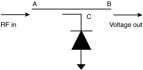
Figure 4-22. Block diagram of a detector.
The Detector's Function
A block diagram of a detector is shown in Figure 4-22, and if you think a detector looks like a cross between a coupler and attenuator, you're right, but that won't help you much. A detector is essentially a power-to-voltage converter. RF power enters at point A and what comes out at point B is a voltage which is proportional to the RF power.
The reason a detector is used, in place of a coupler, is that there are certain pieces of test equipment and non-RF components (like microprocessors) which cannot handle RF power directly, but can handle an electrical ...
Get Essential Guide to RF and Wireless, The now with the O’Reilly learning platform.
O’Reilly members experience books, live events, courses curated by job role, and more from O’Reilly and nearly 200 top publishers.

