Make the Gadget
Parts
- Arduino
- Breadboard
- Mini Sound Sensor microphone (Emartee part number 42021)
- 5–10 LEDs, one or more colors, or LED bar display
- 220-ohm resistor
- 10–15 jumper wires in varied colors
Breadboard the Circuit
You can see what the final build looks like in the breadboard view of this circuit in Figure 2-2.
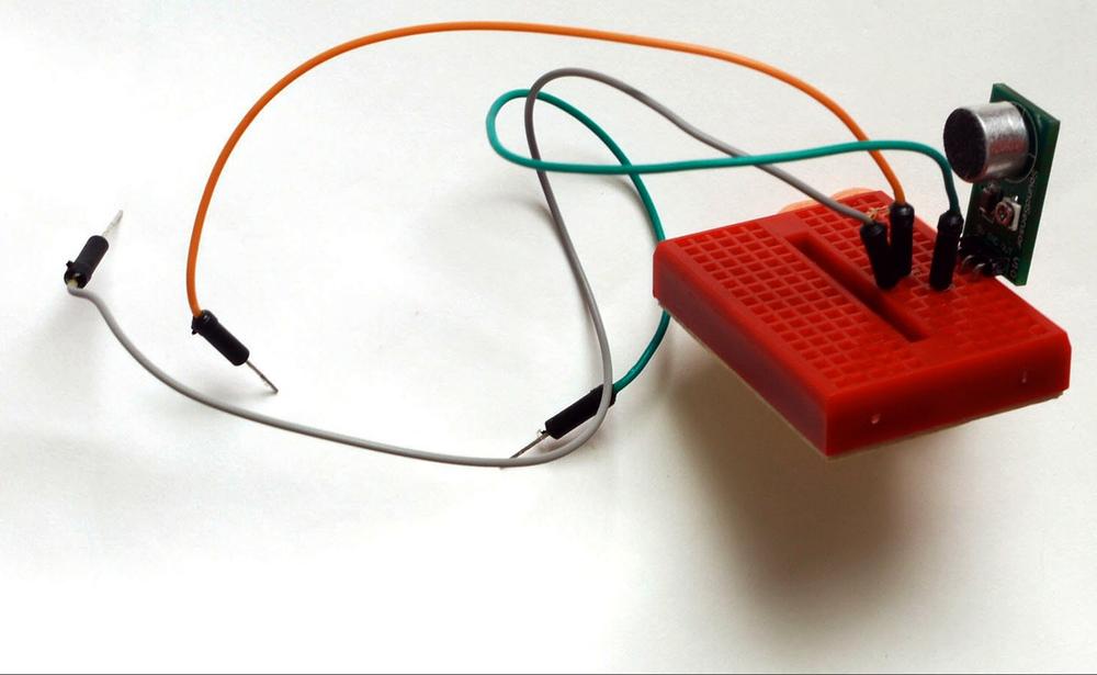
Figure 2-2. The completed noise monitor circuit.
Here’s how to build that circuit:
Step 1 Plug the microphone into the breadboard (see Figure 2-3).
Step 2 Connect a wire between the GND pin of the microphone and the GND pin of Arduino.
Step 3 Connect the power pin of the microphone to the power pin of Arduino.
Step 4 Connect the DATA pin of the microphone to the Analog 0 pin of Arduino.
Step 5 Connect the Digital 2 pin of Arduino to a point on the breadboard.
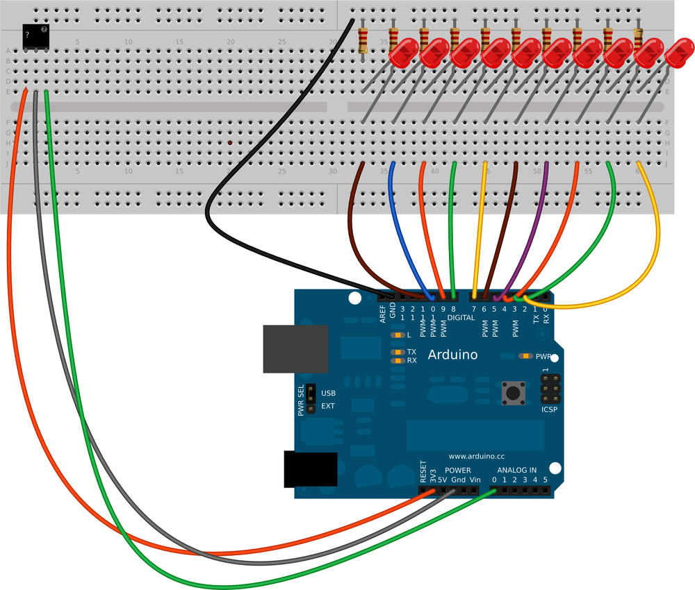
Figure 2-3. The noise sensor plugged to the breadboard, with jumper wires leading from its GND, power, and DATA pins.
Step 6 Connect the LONG or ANODE lead of an LED (or the ANODE lead of an LED bar) to a pin in the same breadboard row as the jumper from D2. Have the LED straddle the breadboard trench, and plug the SHORT lead or CATHODE (or the CATHODE lead of an LED bar) to a pin in the corresponding row on the other side of the breadboard.
Step 7 Plug a 220-ohm resistor into the breadboard, connecting the cathode row ...
Get Environmental Monitoring with Arduino now with the O’Reilly learning platform.
O’Reilly members experience books, live events, courses curated by job role, and more from O’Reilly and nearly 200 top publishers.

