CHAPTER 5
AUXILIARY AND SECTION VIEWS
 AUXILIARY VIEWS
Introduction
Recall that in a multiview drawing of an object with an inclined surface, in one multiview the inclined surface is seen on edge, whereas in the other two multiviews the inclined surface appears as a foreshortened (i.e., not true-size) surface. In Figure 5-1, for example, the inclined surface labeled A is seen on edge in the top view, and as a foreshortened surface in the front and right views. In some circumstances though, a view showing the true size of an inclined surface is useful.
From descriptive geometry1 it is known that the true size and shape of a planar face (or the true length of a line) can be represented in an orthographic projection only if the line of sight is normal to the planar face, or, equivalently, if the projection plane is parallel to the face. This knowledge will be put to use to find the true size of an inclined surface.
Definitions
In earlier chapters we saw that multiview projection is an orthographic projection technique wherein a three-dimensional object is projected onto one of three mutually perpendicular planes.
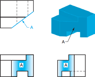
Figure 5-1 Views of cut block with an inclined surface
These are the principal planes: horizontal, frontal, and profile. An auxiliary view is an orthographic view that is projected ...
Get Engineering Design Graphics: Sketching, Modeling, and Visualization, 2nd Edition now with the O’Reilly learning platform.
O’Reilly members experience books, live events, courses curated by job role, and more from O’Reilly and nearly 200 top publishers.

