CHAPTER 4
RT-LEVEL COMBINATIONAL CIRCUIT
The gate-level circuits discussed in Chapter 2 utilize simple logical operators to describe gate-level design, which is composed of simple logic cells. In this chapter, we examine the HDL description of module-level circuits, which are composed of intermediate-sized components, such as adders, comparators, and multiplexers. Since these components are the basic building blocks used in register transfer methodology, it is sometimes referred to as RT-level design. We first discuss more sophisticated Verilog operators, the always block, and routing constructs, and then demonstrate the RT-level combinational circuit design through a series of examples.
4.1 OPERATORS
Verilog consists of about two dozen operators. In addition to the bitwise operators discussed in Chapter 2, there are arithmetic, shift, and relational operators. These operators correspond to intermediate-sized components, such as adders and comparators. We examine these operators in this section and also cover miscellaneous synthesis-related Verilog constructs. Table 4.1 summarizes the operators.
Table 4.1 Verilog operators
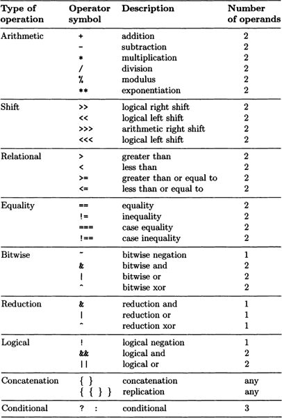
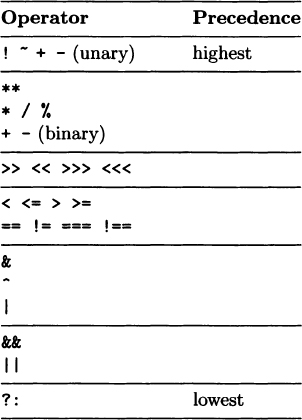
Table 4.2 Operator precedence
4.1.1 Arithmetic operators
There are six arithmetic operators: +, −, *, /, %, and **. They represent addition, subtraction, multiplication, ...
Get Embedded SoPC Design with Nios II Processor and Verilog Examples now with the O’Reilly learning platform.
O’Reilly members experience books, live events, courses curated by job role, and more from O’Reilly and nearly 200 top publishers.

