Chapter 4. Diodes
4.0 Introduction
The first diodes to be used in electronics were cat’s whisker detectors used in crystal radios. These comprised a crystal of a semiconductor material (often lead sulphide or silicon). The cat’s whisker is simply a bare wire that is held in an adjustable bracket that touches the semiconductor crystal. By carefully moving the whisker around, at certain points of contact the arrangement would act as a diode, only allowing current to flow in one direction. This property is needed in a simple radio receiver to detect the radio signal so that it can be heard (see Chapter 19).
Today diodes are much easier to use and come in all sorts of shapes and sizes.
4.1 Block the Flow of Current in One Direction
Solution
A diode is a component that only allows current to flow through it in one direction. It’s a kind of one-way valve if you want to think of it in terms of water running through pipes, which of course is a simplification. In reality the diode offers very low resistance in one direction and very high resistance in the other. In other words, the one-way valve restricts the flow a tiny bit when open and also leaks slightly when closed. But most of the time, thinking of a diode as a one-way valve for electrical current works just fine.
There are lots of specialized types of diodes, but let’s start with the most common and basic diode, the rectifier diode. Figure 4-1 shows such a diode in a circuit with a battery and resistor.
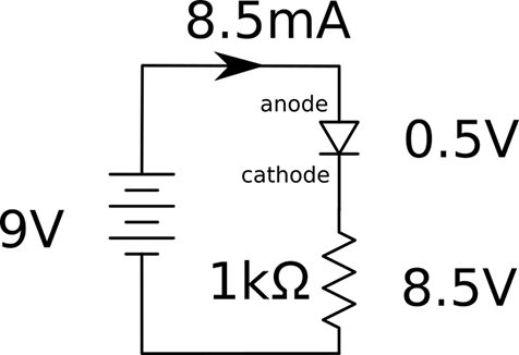
Figure 4-1. A Forward-biased Diode
In this case, the diode allows flow of current and is considered forward-biased. The two leads of the diode are called the anode (abbreviated as “a”) and cathode (abbreviated rather confusingly as “k”). For a diode to be forward-biased, the anode needs to be at a higher voltage than the cathode, as shown in Figure 4-1.
One interesting property of a forward-biased diode is that unlike a resistor, the voltage across it does not vary in proportion to the current flowing through it. Instead, the voltage remains almost constant, no matter how much current flows through it. This varies depending on the type of diode, but is generally about 0.5V.
In the case of Figure 4-1, we can calculate that the current flowing through the resistor will be:
This is only 0.5mA less than if the diode were to be replaced with wire.
In Figure 4-2 the diode is facing the other direction. It is reverse-biased and consequently almost no current will flow through the resistor.
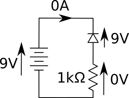
Figure 4-2. A Reverse-biased Diode
Discussion
The diode’s one-way effect can be used to convert AC (Recipe 1.7) into DC. Figure 4-3 shows the effect of a diode on an AC voltage source.
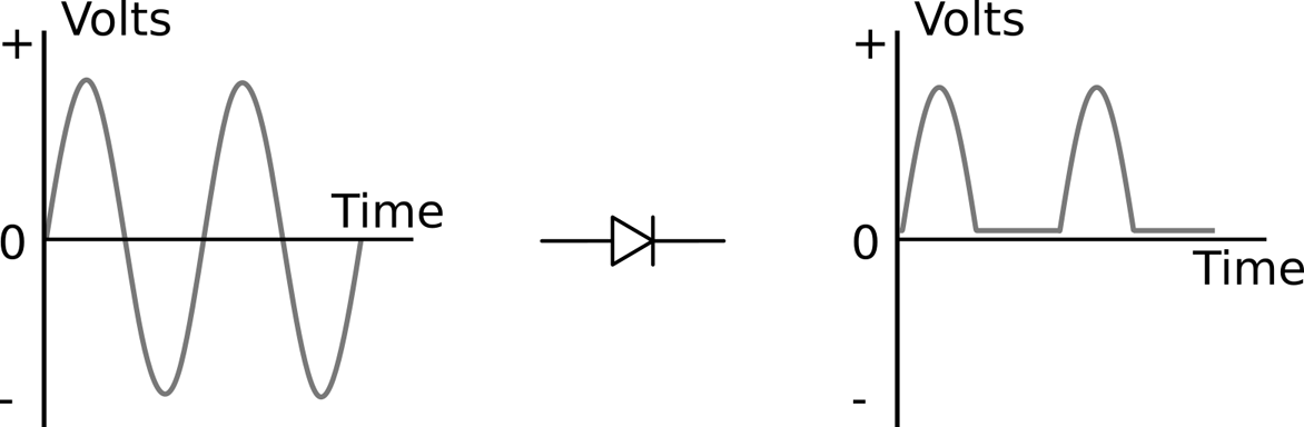
Figure 4-3. Rectification
This effect is called rectification (see Recipe 7.2). The negative part of the cycle is unused. This still isn’t true DC because even though the voltage never becomes negative it still swings from 0V up to a maximum and back down rather than remain constant. The next stage would be to add a capacitor in parallel with the load resistor that would smooth out the signal to a flat and almost constant DC voltage.
See Also
For information on using diodes in power supplies, see Recipe 7.2 and Recipe 7.3.
4.2 Know Your Diodes
Solution
Figure 4-4 shows different types of diodes. Generally, the bigger the diode package, the greater its power-handling capability. Most diodes are a black plastic cylinder with a line at one end that points to the cathode (the end that should be more negative for forward-biased operation).
The diode on the left of Figure 4-4 is an SMD. The through-hole diodes to the right get larger, the higher the current rating.
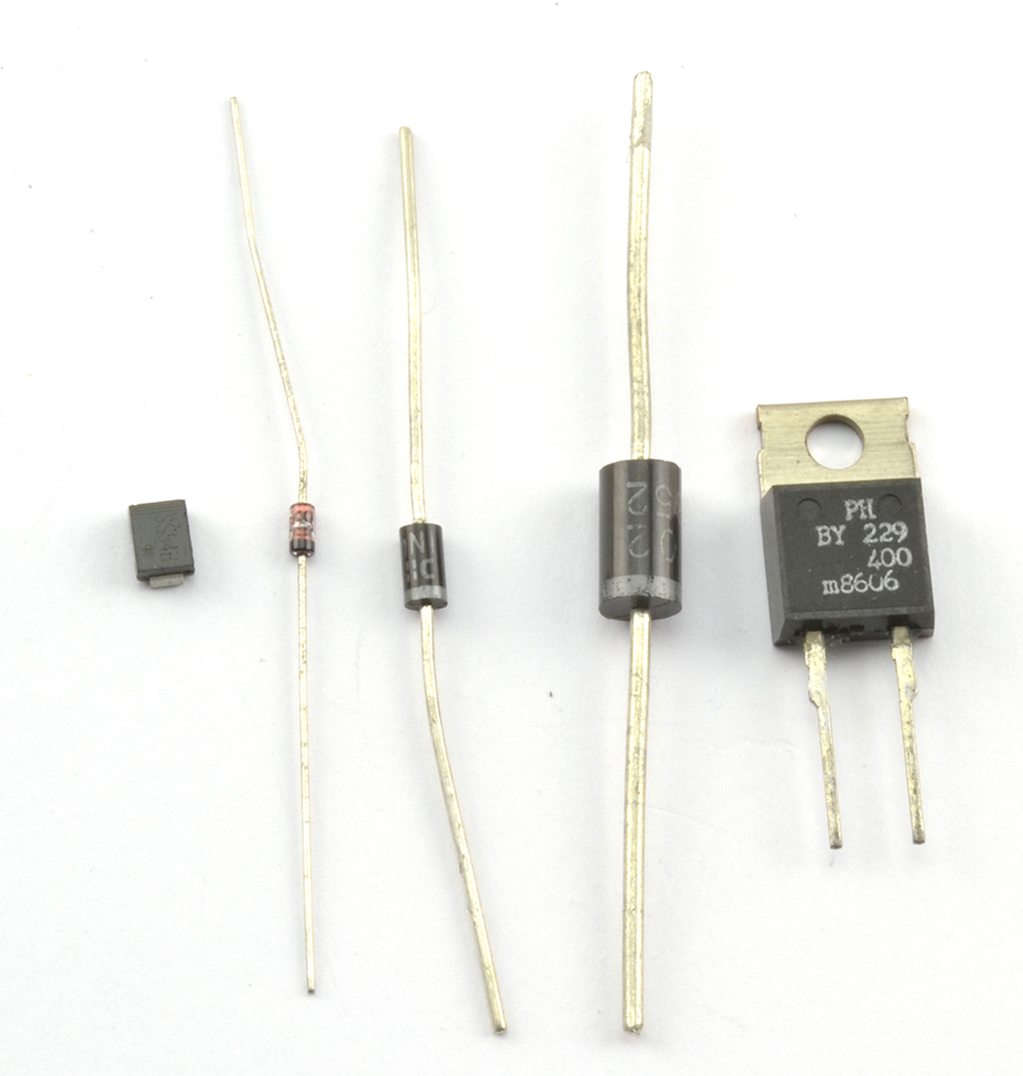
Figure 4-4. A Selection of Diodes
Discussion
There are many different types of diodes. Unlike resistors that are bought as a particular value resistor (say, 1kΩ) diodes are identified by the manufacturer’s part number.
Some of the most commonly used rectifier diodes are listed in Table 4-1.
| Part Number | Typical Forward Voltage | Maximum Current | DC Blocking Voltage | Recovery Time |
|---|---|---|---|---|
| 1N4001 | 0.6V | 1A | 50V | 30µs |
| 1N4004 | 0.6V | 1A | 400V | 30µs |
| 1N4148 | 0.6V | 200mA | 100V | 4ns |
| 1N5819 | 0.3V | 1A | 40V | 10ns |
The forward voltage, often abbreviated as Vf, is the voltage across the diode when forward-biased. The DC-blocking voltage is the reverse-biased voltage that if exceeded may destroy the diode.
The recovery time of a diode refers to how quickly the diode can switch from forward-biased conducting to reverse-biased blocking. This is not instantaneous in any diode and in some applications fast switching is needed.
The 1N5819 diode is called a Schottky diode. These types of diodes have much lower forward voltage and generate less heat.
See Also
You can find the datasheet for the 1N4000 family of diodes here: http://bit.ly/2lOtD71.
4.3 Use a Diode to Restrict DC Voltages
Solution
When forward-biased, Zener diodes behave just like regular diodes and conduct. At low voltages, when reverse-biased they have high resistance just like normal diodes. However, when the reverse-biased voltage exceeds a certain level (called the breakdown voltage), the diodes suddenly conduct as if they were forward-biased.
In fact, regular diodes do the same thing as Zener diodes but at a high voltage and not a voltage that is carefully controlled. The difference with a Zener diode is that the diode is deliberately designed for this breakdown to occur at a certain voltage (say, 5V) and for the Zener diode to be undamaged by such a “breakdown.”
Discussion
Zener diodes are useful for providing a reference voltage (see the schematic in Figure 4-5). Note the slightly different component symbol for a Zener diode with the little arms on the cathode.

Figure 4-5. Using a Zener Diode to Provide a Reference Voltage
The resistor R limits the current flowing through the Zener diode. This current is always assumed to be much greater than the current flowing into a load across the diode.
This circuit is only well suited to providing a voltage reference. A voltage reference provides a stable voltage but with hardly any load current; for example, when the circuit is used with a transistor as in Recipe 7.4. So a resistor value of, say, 1kΩ would, if Vin was 12V, allow a current of:
The output voltage will remain roughly 5V whatever Vin is as long as it’s greater than 5V. To understand how this happens, imagine that the voltage across the Zener diode is less than its 5V breakdown voltage. The Zener’s resistance will therefore be high and so the voltage across it due to the voltage divider effect of R and the Zener will be higher than the breakdown voltage. But wait, since the breakdown voltage is exceeded it will conduct, bringing the Vout down to 5V. If it falls below that, the diode will turn off and the Vout will increase again.
Zener diodes are also used to protect sensitive electronics from high-voltage spikes due to static discharge or incorrectly connected equipment. Figure 4-6 shows how an input to an amplifier not expected to exceed ±10V can be protected from both high positive and negative voltages. When the input voltage is within the allowed range the Zener will be high resistance and not interfere with the input signal, but as soon as the voltage is exceeded in either direction the Zener will conduct the excess voltage to ground.
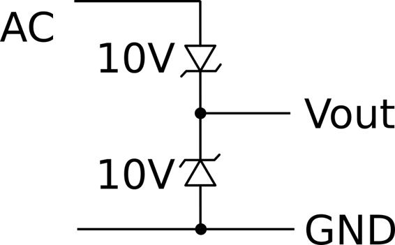
Figure 4-6. Protecting Inputs from Over-Voltage
See Also
Although you would generally use a voltage-regulator IC (see Recipe 7.4), you can use a Zener diode combined with a transistor to act as a voltage regulator.
4.4 Let There Be Light
Solution
LEDs are like regular diodes in that when reverse-biased they block the flow of current, but when forward-biased they emit light.
The forward voltage of an LED is more than the usual 0.5V of a rectifier and depends on the color of the LED. Generally a standard red LED will have a forward voltage of about 1.6V.
Discussion
Figure 4-7 shows an LED in series with a resistor. The resistor is necessary to prevent too much current from flowing through the LED and damaging it.
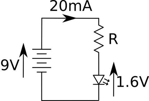
Figure 4-7. Powering an LED
An LED used as an illuminator will generally emit some light at 1mA but usually needs about 20mA for optimum brightness. The LED’s datasheet will tell you its optimal and maximum forward currents.
As an example, if in Figure 6-5 the voltage source is a 9V battery and the LED has a forward voltage of 1.6V, you can calculate the resistor value needed using Ohm’s Law:
370Ω is not a common resistor value (see Recipe 2.2) so you could pick a 360Ω resistor, in which case the current would be:
which would be just fine.
Finding suitable resistor values for LEDs to limit the current is such a common task that there is really no need to go through these calculations all the time. In Recipe 14.1 you will find a practical recipe for rule-of-thumb selection of current-limiting resistors.
See Also
For information on driving different types of LED, see Chapter 14.
4.5 Detect Light
Solution
Use a photodiode. You can also use a photoresistor (Recipe 2.8) or a phototransistor (Recipe 5.7).
A photodiode is a diode that is sensitive to light. A photodiode usually has a transparent window, but photodiodes designed for infrared use have a black plastic case. The black plastic case is transparent to IR and usefully stops the photodiode from being sensitive to visible light.
Photodiodes can be treated as little tiny photovoltaic solar cells. When illuminated they generate a small current. Figure 4-8 shows how you can use a photodiode with a resistor to produce a small voltage that you could then use in your circuits.
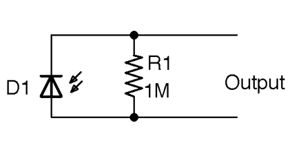
Figure 4-8. A Photodiode in Photovoltaic Mode
In this circuit, the voltage when illuminated brightly might only be 100mV.
The resistor is necessary so that the small current from the photodiode is converted into a voltage (V=IR). Otherwise, any voltage that you measure will be depend on the resistance (called impedance when not from a resistor) of whatever is measuring the voltage. So, for example, a multimeter with an input impedance of 10MΩ would provide a completely different (and lower) reading than a multimeter with a 100MΩ input impedance.
R1 makes the voltage consistent. The impedance of whatever is connected to the output needs to be much higher in value than R1. If this is an op-amp (see Chapter 17) then the input impedance is likely to be hundreds of MΩ and so will not alter the output voltage appreciably. The smaller you make R1, the lower the output voltage will be, so it’s a matter of striking a balance.
Better sensitivity can be achieved by using the photodiode in a photoconductive mode with a voltage source (Figure 4-9).
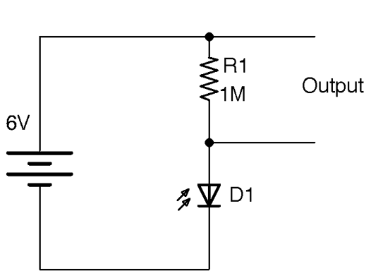
Figure 4-9. A Photodiode in Photoconductive Mode
See Also
Photoresistors (Recipe 12.6) and phototransistors (Recipe 5.7) tend to be used more than photodiodes as they are more sensitive.
Get Electronics Cookbook now with the O’Reilly learning platform.
O’Reilly members experience books, live events, courses curated by job role, and more from O’Reilly and nearly 200 top publishers.

