Appendix E
Separation of No-load Losses of an Induction Motor
To separate the no-load losses (iron losses and mechanical losses) of a three-phase squirrel cage induction motor, the circuit connection is made as shown in Figure E.1.
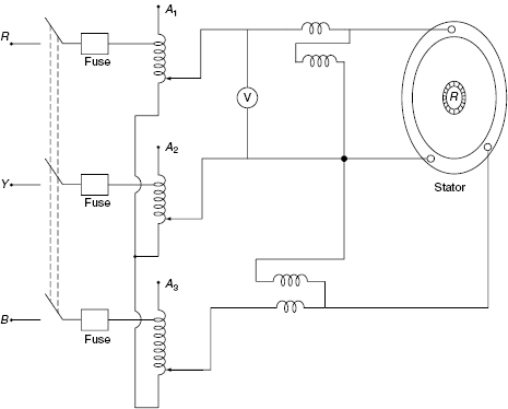
Figure E.1 Circuit Diagram
The name plate details of the motor and the autotransformer should be noted at first. The required apparatuses are ammeter, voltmeter, wattmeter, three-phase autotransformer and rheostat. The autotransformer’s initial position must be in the minimum voltage position and the motor need not to be loaded throughout the experiment. The required table (Table E.1) is shown in Figure E.1.
Table E.1 ...
Get Electrical Machines, 2nd Edition now with the O’Reilly learning platform.
O’Reilly members experience books, live events, courses curated by job role, and more from O’Reilly and nearly 200 top publishers.

