5.3 SUBSTITUTION THEOREM
Consider the three-mesh circuit shown in Fig. 5.3-1. Mesh analysis reveals that the mesh currents are 1 A, 2 A and 3 A as shown in the figure. Two nodes a and a′ have been identified in the circuit and the current crossing the node a from left to right is marked as 2 A. The voltage of a with respect to a′ is calculated to be 1 V and is marked in the figure.
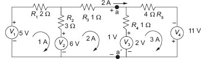
Fig. 5.3-1 A Three-mesh Circuit with Two Nodes – a and a′ – Identified
Now, we add two current sources between the two nodes, a and a′, as shown in Fig. 5.3-2. The current sources have equal and opposite currents of 2 A magnitude.
Fig. 5.3-2 Circuit in ...
Get Electric Circuits and Networks now with the O’Reilly learning platform.
O’Reilly members experience books, live events, courses curated by job role, and more from O’Reilly and nearly 200 top publishers.

