10.13 PROBLEMS
(Initial current in inductor is zero unless stated otherwise.)
1. The switch S1 in the circuit in Fig. 10.13-1 is closed at t = 0 and the switch S2 is closed at t = 0.12 s. Both switches are ideal. (i) Find the current in the inductance as a function of time and plot it. (ii) Find the voltage across the inductance and plot it. (iii) Find the voltage across the first resistor and plot it. (iv) What is the time required to attain 90% of the final steady state value of current?
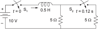
Fig. 10.13-1
2. Initial current at t = –∞ in the inductor in the circuit in Fig. 10.13-2 was zero. Find iL(t) and vL(t) for t ≥ 0+ and plot them.
Get Electric Circuits and Networks now with the O’Reilly learning platform.
O’Reilly members experience books, live events, courses curated by job role, and more from O’Reilly and nearly 200 top publishers.

