The ubiquitous “Hello World” application that every programmer starts off with when faced with a new language has a hardware equivalent: blinking an LED on and off. It doesn’t sound too hard. But ten years ago, building even simple hardware was a lot harder than it is now.
Typically, a microprocessor used to arrive on a proprietary development board, along with a compiler on a CD ROM. Loading the compiler onto your computer took several hours. Then you had to locate the correct drivers to tell your computer how to talk to the evaluation hardware. Then you had to install the drivers and—if everything worked—by the end of the first day your compiler might just be talking to the evaluation board with your microprocessor.
The next day you needed to download the manufacturer’s sample applications, which would be written in machine code. From there, you probably had to spend another day configuring you compiler and addressing linking issues before getting the code working on the evaluation hardware. If everything went smoothly, it would take only a day or two to get to a blinking LED. If you weren’t as lucky, it might take a week, even for someone familiar with hardware.
Then, if you wanted to change the blink rate of your LED, you have to do a lot of reading about the architecture of your chip—one of hundreds of different processor all with subtly different architectures—and figure out how registers and timer interrupts worked for your architecture. This whole process took days, if not weeks, and in the mid-nineties a reasonably brief walkthrough of the process would take several hundred pages to explain it properly. Even ten years after that, it was still probably the best part of seventy pages to reach a working application. We’re going to manage it over the course of the next few pages.
In the last several years, all this has changed. Every so often, a piece of technology can become a lever that lets people move the world, just a little bit. The Arduino is one of those levers.
It started off as a project to give artists access to embedded microprocessors for interaction design projects, but it may well end up in a museum as one of the building blocks of the modern world. It allows rapid, cheap prototyping for embedded systems. It turns what used to be fairly tough hardware problems into simpler software problems (and we know that once problems are in software, they become almost exponentially easier).
The Arduino—and the open hardware movement that has grown up with it, and at least to a certain extent around it—is enabling a generation of high-tech tinkerers both to break the seals on proprietary technology and to prototype new ideas with fairly minimal hardware knowledge. This Maker renaissance has led to an interesting growth in innovation. People aren’t just having ideas, they’re doing something with them.
The current revision of the Arduino board is known as the Arduino Uno (see Figure 1-1). This board is based on the ATmega328 microcontroller.
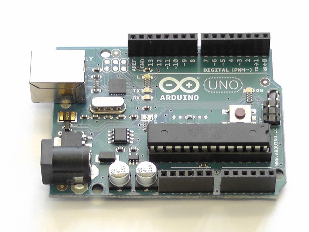
It has fourteen digital input/output pins, six of which can be used as PWM outputs, along with six more analog input pins (see Table 1-1).
Table 1-1. Technical specification of the Arduino Uno board
Arduino Uno | |
|---|---|
Microcontroller | ATmega328 |
Operating Voltage | 5 V |
Input Voltage (recommended) | 7 – 12 V |
Input Voltage (limits) | 6 – 20 V |
Digital I/O Pins | 14 (6 provide PWM) |
Analog Input Pins | 6 |
DC Current per I/O Pin | 40 mA |
DC Current for 3.3V Pin | 50 mA |
Flash Memory | 32 KB |
SRAM | 2 KB |
EEPROM | 1 KB |
Clock Speed | 16 MHz |
The Arduino platform has everything needed to support the on-board microcontroller. It is attached directly to your Mac for programming using a USB connection, and it can be powered via the same USB connection, or with an external power supply if you want to detach the board from your Mac once you’ve programmed it.
Note
To keep things short, this tutorial will assume you’re using a recent Arduino board such as the Arduino Uno, Duemilanove, or Diecimila. However, if you’re working with an older board or one of the many Arduino-compatible clones, it’s likely that little needs to be changed. See this Arduino site for links to the Getting Started guides for various other boards.
The Arduino Uno can be powered via the USB connection, or with an external power supply. Unlike previous generations of the Arduino, the power source is selected automatically. If you’re using an earlier model, you will have to manually change between USB and external power sources using a jumper on the board itself; this jumper is usually located between the USB and power jacks.
The board can operate on an external supply of 6 to 20 volts. However, if supplied with less than 7V, the 5V pin may supply less than nominal voltage and the board may become unstable. If using more than 12V, the voltage regulator may overheat and damage the board. The recommended range is therefore between 7 to 12 volts.
Each of the 14 pins on the Uno can be used as an input or output. They operate at 5V, with each pin having an internal pull-up resistor (disconnected by default) of 20-50 kOhms. The maximum current that a pin can provide is 40mA.
Note
Some pins have specialized functions. Perhaps the most important of these to us for the purposes of this book are pins 0 and 1. These pins can be used to receive (RX) and transmit (TX) TTL serial data. These pins are connected to the corresponding pins of the ATmega8U2 USB-to-TTL Serial chip.
The ATmega328 provides UART TTL serial communication at 5V, which is available on digital pins 0 (RX) and 1 (TX). The Arduino Uno has an ATmega8U2 chip on-board that redirects this serial communication over USB, allowing the Arduino to appear as a virtual serial port to software on your Mac. If you’re using an older board, such as the Duemilanove or Diecimila, these boards make use of the FTDI USB-to-serial driver chip to accomplish the same task, although unlike with the newer Uno board, you will be required to install a driver so that your Mac can see the board correctly.
Download the latest version of the development environment from the Arduino.cc website.
Note
The latest version of the Arduino development environment is Arduino 1.0.3, at the time of writing.
Like most Mac applications,[1] the development environment comes as a disk image (.dmg file) that should mount automatically after you have downloaded it. If it doesn’t, double-click on it to open it manually. After it is open, just click-and-drag the Arduino.app application into your /Applications folder. If you’re using an older board that requires that you install the FTDI USB-to-Serial drivers, you should also double-click on the FTDIUSBSerialDriver.mpkg file included in the disk image to install the necessary drivers.
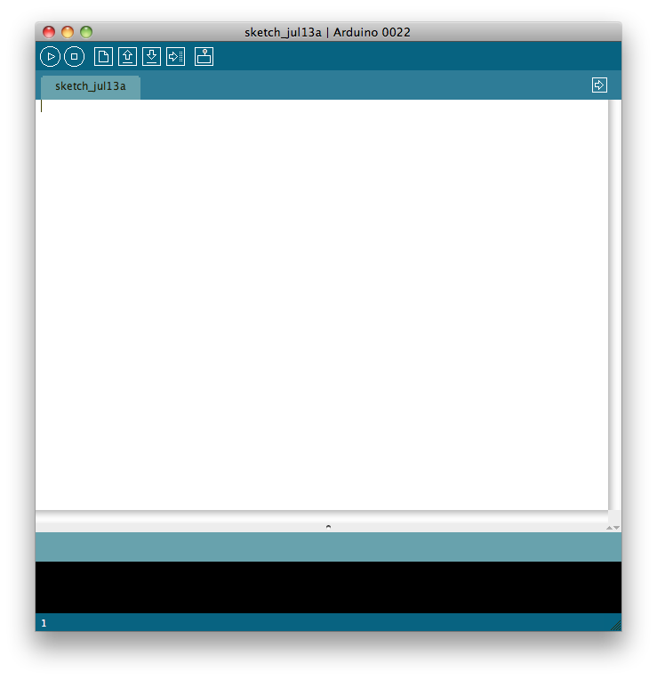
Once you’ve installed the development environment, eject the disk image by dragging it to the trashcan and double-click on the Arduino.app application icon to start the IDE. You should see something that looks a lot like Figure 1-2.
Connect the Arduino to your Mac with an appropriate USB cable. In
the case of an Arduino Uno, Duemilanove, or Diecimila, you’ll need a
USB-A (Mac) to USB-B (Arduino) cable: the same sort needed for most USB
printers. The green power LED (labeled PWR) should go on, and if you’re using the
Arduino Uno, a dialog box will appear telling you that a new network
interface has been detected. Just hit the Apply button. While the new
interface will claim to be “Not Configured,” if you inspect it in System
Preferences, it is working correctly.
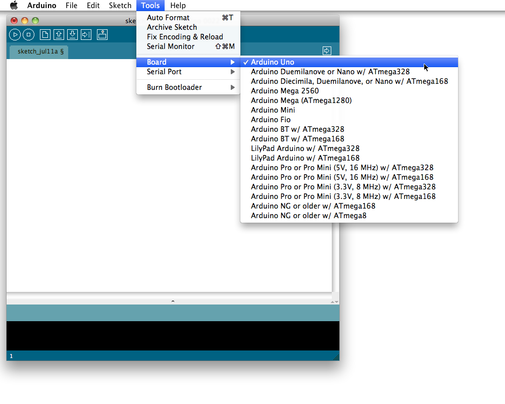
After connecting your board to your Mac, go to the Tools→Board menu item in the Arduino development environment and select your board from the list of supported board in the drop-down menu (see Figure 1-3).
Then go to the Tools→Serial Port menu and select the correct serial port for your board (Figure 1-4). On the Mac, the name will start with /dev/tty.usbmodem for the Uno, or /dev/tty.usbserial for older boards.
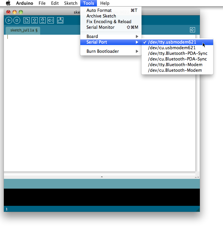
If you’re unsure which serial port corresponds to your board, you can always unplug and then re-plug the USB cable connecting your Mac to the Arduino board to see how the menu changes.
Now that we have our Arduino connected to our Mac, let’s go ahead and walk through the hardware equivalent of “Hello World”: the blinking LED.
Note
An Arduino program is normally referred to as a sketch.
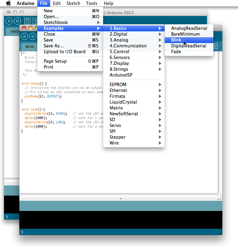
There are a number of example sketches included in the development environment. The one we’re looking for can be found by selecting File→Examples→1.Basics→Blink. The example sketch will open in a new window (see Figure 1-5).
Every Arduino sketch consists of two parts: the setup and the loop.
Every time the board is powered up, or the board’s reset button is pushed,
the setup( ) routine is run. After that
finishes, the board runs the loop( )
routine. When that completes, and perhaps somewhat predictably, the
loop( ) is run again and again.
Effectively, the contents of the loop(
) sit inside an infinite while loop.
Before we go ahead to build and deploy this example to our Arduino, let’s take a look at the code:
void setup() {
pinMode(13, OUTPUT); }
void loop() {
digitalWrite(13, HIGH);
}
void loop() {
digitalWrite(13, HIGH); delay(1000);
digitalWrite(13, LOW);
delay(1000);
}
delay(1000);
digitalWrite(13, LOW);
delay(1000);
}-
Arduino pins default to INPUT. However, here we set pin 13 to behave as an OUTPUT pin. In this state, the pin can provide up to 40 mA of current to other devices. This is enough current to brightly light up an LED, or run many sensors, but not enough current to run most relays, solenoids, or motors. See this Arduino site.
-
If the pin has been configured for OUTPUT, its voltage will be set to the corresponding value: 5V for
HIGH, 0V (ground) forLOW.
Effectively, then, this piece of code causes the voltage on pin 13
to be brought HIGH for a second
(1,000 ms) and then LOW for a
further second before the loop starts again, bringing the voltage
HIGH once more.
As mentioned before, some of the digital pins on the Arduino board have special functions; pin 13 is one of these. On most boards (including the Uno), it has an LED and resistor attached to it that’s soldered onto the board itself. Therefore, the effect of this sketch will be to turn the embedded LED on and off with a periodicity of 1 second.
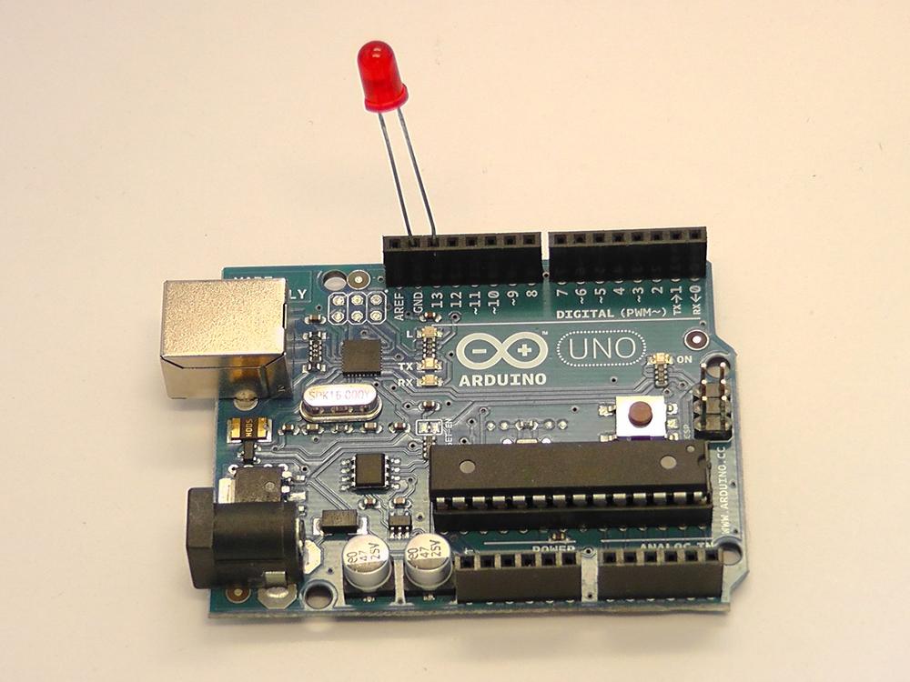
While there is already a built-in LED on the board, this is going to look more impressive if we add a “real” LED as well. Any LED will do, but LEDs are directional components and must not be inserted backwards. Look carefully at the two legs of the LED; one should be shorter than the other. The shorter leg corresponds to the ground, while the longer leg is the positive.
Insert the short leg into the GND pin, and the longer leg into the pin 13, as shown in Figure 1-6.
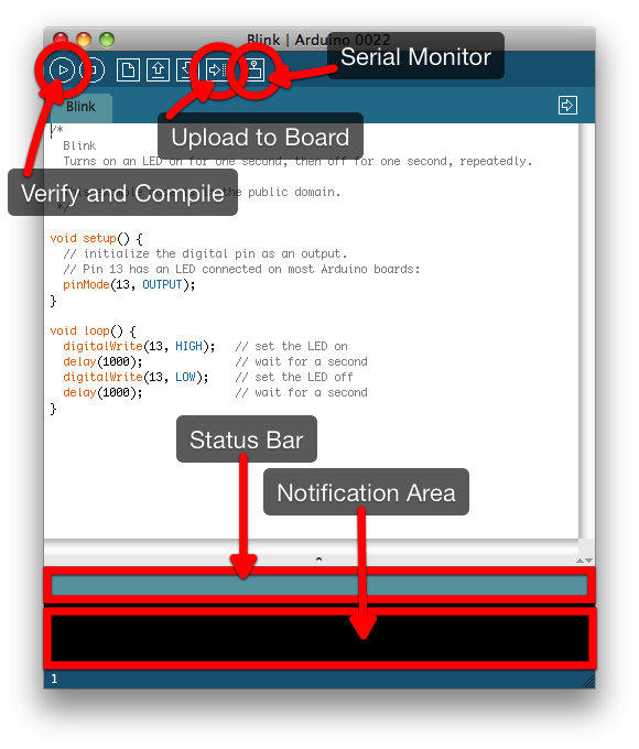
The first step to getting the sketch ready for transfer over to the Arduino is to click on the Verify/Compile button (see Figure 1-7). This will compile your code, checking it for errors, and then translate you program into something that is compatible with the Arduino architecture. After a few seconds, you should see the message “Done compiling.” in the Status Bar and something along the lines of “Binary sketch size: 1018 bytes (of a 32256 byte maximum)” in the Notification area.
Once you see that message, go ahead and click on the Upload button (see Figure 1-7 again). This will initiate the transfer of the compiled code to the board via the USB connection.
Wait a few seconds—you should see the RX and TX LEDs on the board flashing as the data is transferred over the serial connection from your Mac to the board. If the upload is successful, the message “Done uploading.” will appear in the status bar.
A few seconds after the upload finishes, you should see the pin 13 LED on the board (labeled L on the PCB) start to blink (in orange) along with the LED we inserted into pin 13. One second on, one second off. If you see that: congratulations, you’ve just successfully gotten the hardware equivalent of “Hello World” to compile and run on the Arduino board.
Now that we’ve seen how a basic Arduino sketch works, let’s move on to sending and receiving data from the Arduino board. We need to know how to do this, because this is how we’ll control the Arduino or get sensor readings when we connect it to our iOS devices. For now, however, we’re going to use the Serial Monitor (see Figure 1-7 again) inside the development environment.
Open a new sketch by clicking on File→New (⌘N) to open a new window.
void setup() {
  Serial.begin(9600);
}

void loop() {
  while (Serial.available() <= 0) {
    Serial.println("Hello world");
    delay(300);
  }
}
delay(300);
}
}-
Sets the data rate in bits per second (baud) for serial data transmission.
-
Here we get the number of bytes available for reading from the serial port. If there are no bytes waiting in the buffer, we loop until some arrive.
-
Finally, here inside the loop we print “Hello World” to the serial connection.
Effectively, this code will send the string “Hello World” to the serial connection every 300 ms until the board receives a byte (character), at which point it will stop.
Save the contents of the sketch to a file using the File→New (⌘S) menu item, and then click on the Verify button to compile your sketch—and, if all goes well, the Upload button to upload it to the board. You should see the RX and TX LEDs light up as the code is transferred. When you see the “Done uploading.” message in the status bar, click on the Serial Console button (see Figure 1-7 again) in the development environment to open the serial console.
Doing so will reset the Arduino, at which point you should see the phrase “Hello World” appear on the console every 300 ms (see Figure 1-8) accompanied by a flash of the TX LED on the Arduino board itself.
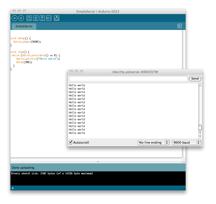
Entering a character or string in the text entry box and hitting the Send button will transmit those characters to the board, at which point the board should stop sending the string “Hello world” to the serial port.
Let’s make that a bit more specific. Add the following bolded lines to your sketch and re-upload it to the Arduino:
void setup() {
  Serial.begin(9600);
}

void loop() {
  while (Serial.available() <= 0) {
    Serial.println("Hello world");
    delay(300);
  }

  Serial.println("Goodbye world");
  while(1) { }
}
The Serial Console will close automatically when you upload new code to the board, so reopen it and you should see things much as before (Figure 1-8). However, this time, if you send a string to the board, you should receive the string “Goodbye world” back.
In this chapter we’ve learned how to use the microcontroller to blink an LED, as well as how to get messages from, and send messages to, the board from our computer. In the next chapter we’ll start building out sensor mote platform.
Get Distributed Network Data now with the O’Reilly learning platform.
O’Reilly members experience books, live events, courses curated by job role, and more from O’Reilly and nearly 200 top publishers.

