6.3. Data representation
The general shape of an adaptive filter might be the following.
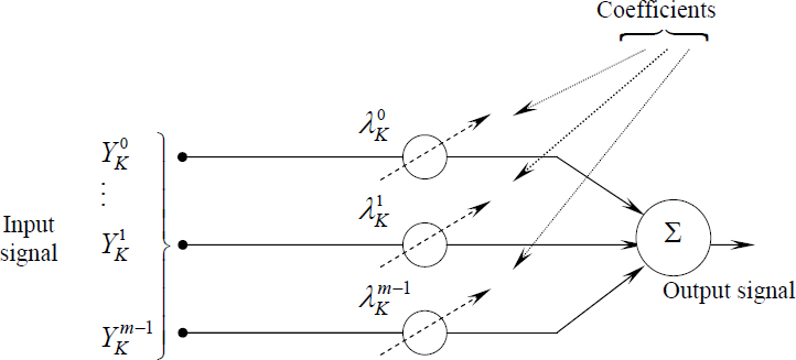
Figure 6.7. Theoretical schema with multiple inputs
The input signal can be simultaneously the result of sensors (case of adaptive antennae, for example) or as well they can represent the different samples, taken at different instants of a single signal.
We will take as notation:
– multiple input: ![]() ;
;
– single input: ![]() .
.
In the case of a single input that we will consider next, we will have the following configuration.
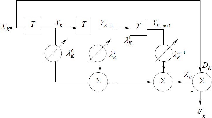
Figure 6.8. Schema of predictor principle
XK, YK, ZK, DK and ![]() representing the signal to be predicted, the filter input, the filter output, the desired output and the signal error respectively.
representing the signal to be predicted, the filter input, the filter output, the desired output and the signal error respectively.
Let us write the output ZK:
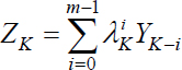
By calling λK the weight vector or coefficient vector at instant “K”, also written in the form , we can use a single vectorial notation:
Our system not being perfect we ...
Get Discrete Stochastic Processes and Optimal Filtering now with the O’Reilly learning platform.
O’Reilly members experience books, live events, courses curated by job role, and more from O’Reilly and nearly 200 top publishers.

