B
Registers for Circular Addressing and Interrupts
A number of special-purpose registers available on the C6x processor are shown in Figures B.1 to B.8 [1].
1. Figure B.1 shows the address mode register (AMR) that is used for the circular mode of addressing. It is used to select one of eight register pointers (A4 through A7, B4 through B7) and two blocks of memories (BK0, BK1) that can be used as circular buffers.
2. Figure B.2 shows the control status register (CSR) with bit 0 for the global interrupt enable (GIE) bit.
3. Figure B.3 shows the interrupt enable register (IER).
4. Figure B.4 shows the interrupt flag register (IFR).
5. Figure B.5 shows the interrupt set register (ISR).
6. Figure B.6 shows the interrupt clear register (ICR).
7. Figure B.7 shows the interrupt service table pointer (ISTP).
8. Figure B.8 shows the serial port control register (SPCR).
In Section 3.7.2 we discuss the AMR register and in Section 3.14 the interrupt registers.
REFERENCE
1. C6000 CPU and Instruction Set, SPRU189F, Texas Instruments, Dallas, TX, 2000.
FIGURE B.1 Address mode register (AMR). (Courtesy of Texas Instruments.)
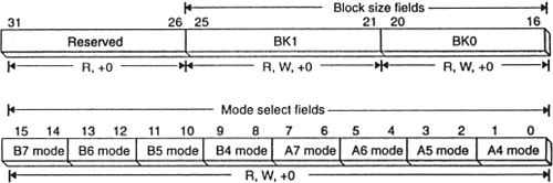
FIGURE B.2 Control status register (CSR). (Courtesy of Texas Instruments.)
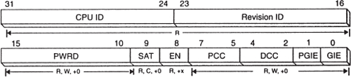
FIGURE B.3 Interrupt enable register (IER). (Courtesy of Texas Instruments.)
FIGURE B.4 Interrupt ...

