DHCP can be used in many different networking environments. Regardless of the networking environment, DHCP in itself operates fundamentally the same. In other words, the server is installed, scopes are created, options are configured, and DHCP clients start receiving address leases. However, depending on the network infrastructure, more planning and configuration may need to take place before DHCP can function efficiently and acceptably. Fortunately, DHCP is very flexible, and a designer can take many different design ideas to create the solution best suited for the environment.
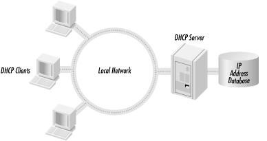
DHCP operating on a single subnet is the simplest DHCP configuration. A single subnet does not include any routers or DHCP relay agents. By simply installing and configuring the DHCP server, DHCP clients can begin allocating dynamic IP addresses.
Designing a DHCP strategy for a non-routed environment consists of determining the hardware requirements of the DHCP server and then deciding which clients will be assigned dynamic addresses and which will be configured with static addresses (typically servers and network printers). Finally, the designer determines which DHCP options need to be used, such as the IP addresses for the DNS and WINS servers on the network.
The network shown in Figure 4.1 consists of a single subnet that includes a DHCP server and several DHCP clients. To begin servicing the clients, the DHCP server needs a single scope whose addresses fall within the range of the subnet. Usually, in this scenario, the default lease duration of 8 days is sufficient.
In a routed environment, more planning must be done in the design phase to create the appropriate DHCP infrastructure. The first step includes the layout of the subnets and deciding the placement of the DHCP servers. This step also includes deciding which fault tolerant strategies should be incorporated into the plan.
The layout of the subnets typically follows the physical layout of the network, such as remote sites or buildings in a campus. The subnet layout can also be determined by function or lines of business, e.g., the sales department and engineering department may be located on separate subnets, although they are both in the same building.
The placement of the DHCP servers can be a little bit trickier. In general, the placement of the DHCP servers should not be determined by the administrative structure of the network (i.e., domains or Active Directory), but by the number of users that need DHCP services. Placement of DHCP servers must also consider fault tolerance strategies so a particular subnet can continuously be serviced by DHCP.
Figure 4.2 shows one possible network topology. By using the data obtained from the network topology, the designer can create a table (see Table 4.1) listing the different sites, the number of users in each site, the subnets that service the site, and the number of addresses available in each subnet.
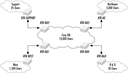
Table 4-1. Network Topology Requirements
|
Site |
Number of Users |
Subnet Address |
Number of Hosts |
|---|---|---|---|
|
Corp HQ |
10,000 |
168.3.4.0 |
1022 |
|
168.3.8.0 |
1022 | ||
|
168.3.12.0 |
1022 | ||
|
168.3.16.0 |
1022 | ||
|
168.3.20.0 |
1022 | ||
|
168.3.24.0 |
1022 | ||
|
168.3.28.0 |
1022 | ||
|
168.3.32.0 |
1022 | ||
|
168.3.36.0 |
1022 | ||
|
168.3.40.0 |
1022 | ||
|
Northeast |
5,000 |
168.3.44.0 |
1022 |
|
168.3.48.0 |
1022 | ||
|
168.3.52.0 |
1022 | ||
|
168.3.56.0 |
1022 | ||
|
168.3.60.0 |
1022 | ||
|
West |
1,500 |
168.3.64.0 |
1022 |
|
168.3.68.0 |
1022 | ||
|
R & D |
50 |
168.3.72.0 |
1022 |
|
Support |
25 |
168.3.76.0 |
1022 |
First, review the number of users that require DHCP in each site. The Corp HQ site, with 10,000 users, definitely needs local DHCP servers. The Northeast site and the West site also require local DHCP servers. The two smaller sites, R & D and Support, have few users. Therefore they can be serviced by one of the DHCP servers back in Corp HQ.
How many DHCP servers are needed? Well, according to Microsoft, the DHCP server in Windows 2000 can handle as many as 100,000 users. So in this case a single DHCP server could handle all user requests from Corp HQ as well as the two small remote sites. However, one reason to have more than one DHCP server is to create a fault tolerant design.
To create fault tolerance, two DHCP servers can be placed in the Corp HQ site and split using the 50/50 scope splitting method. The scopes for the R & D and Support remote sites can also be split 50/50. To complete the fault tolerance plan, the routers connecting the remote sites to Corp HQ need DHCP relay agents configured to point to the DHCP servers.
The remaining two sites, Northeast and West, need one local DHCP server each. The scopes servicing these sites can be split using the 80/20 scope splitting method, with 80% of the addresses assigned to scopes on the local DHCP server and the remaining 20% assigned to scopes located on the Corp HQ DHCP servers. In the event that the DHCP server goes down on either of these sites, the DHCP servers at Corp HQ will service the client requests.
Another option for fault tolerance is the use of DHCP clusters. By replacing all the DHCP servers with DHCP clusters, the design benefits from virtually guaranteed uptime, short of a major disaster such as a power failure or fire.
To take fault tolerance even further, the designer can combine clusters with scope splitting. This ensures that the DHCP service will be available at all times.
A major factor in designing a fault tolerant plan is cost. Each of the scope splitting situations calls for an additional DHCP server. Using clusters drives the costs up further still, since a cluster must contain a minimum of two nodes.
Once server placement and fault tolerance is completed, the designer must begin creating the scopes.
In this scenario, there are a total of 19 subnets. Through scope splitting, there are a total of 38 scopes. Table 4.2 lists the scopes that need to be created.
Table 4-2. Scope Table
|
Site Served |
DHCP Server |
Scope |
Address Range |
Number of Addresses |
|---|---|---|---|---|
|
Corp HQ |
DHCP-HQ1 (Cluster) |
168.3.4.0 (50% Scope) |
168.3.4.1 through 168.3.5.255 |
511 |
|
168.3.8.0 (50% Scope) |
168.3.8.1 through 168.3.9.255 |
511 | ||
|
168.3.12.0 (50% Scope) |
168.3.12.1 through 168.3.13.255 |
511 | ||
|
168.3.16.0 (50% Scope) |
168.3.16.1 through 168.3.17.255 |
511 | ||
|
168.3.20.0 (50% Scope) |
168.3.20.1 through 168.3.21.255 |
511 | ||
|
168.3.24.0 (50% Scope) |
168.3.24.1 through 168.3.25.255 |
511 | ||
|
168.3.28.0 (50% Scope) |
168.3.28.1 through 168.3.28.255 |
511 | ||
|
168.3.32.0 (50% Scope) |
168.3.32.1 through 168.3.33.255 |
511 | ||
|
168.3.36.0 (50% Scope) |
168.3.36.1 through 168.3.37.255 |
511 | ||
|
168.3.40.0 (50% Scope) |
168.3.40.1 through 168.3.41.255 |
511 | ||
|
DHCP-HQ2 (Cluster) |
168.3.4.0 (50% Scope) |
168.3.6.0 through 168.3.7.254 |
511 | |
|
168.3.8.0 (50% Scope) |
168.3.10.0 through 168.3.11.254 |
511 | ||
|
168.3.12.0 (50% Scope) |
168.3.14.0 through 168.3.15.254 |
511 | ||
|
168.3.16.0 (50% Scope) |
168.3.18.0 through 168.3.19.254 |
511 | ||
|
168.3.20.0 (50% Scope) |
168.3.22.0 through 168.3.23.254 |
511 | ||
|
168.3.24.0 (50% Scope) |
168.3.26.0 through 168.3.27.254 |
511 | ||
|
168.3.28.0 (50% Scope) |
168.3.30.0 through 168.3.31.254 |
511 | ||
|
168.3.32.0 (50% Scope) |
168.3.34.0 through 168.3.35.254 |
511 | ||
|
168.3.36.0 (50% Scope) |
168.3.38.0 through 168.3.39.254 |
511 | ||
|
168.3.40.0 (50% Scope) |
168.3.42.0 through 168.3.43.254 |
511 | ||
|
Northeast |
DHCP-NE1 (Cluster) |
168.3.44.0 (80% Scope) |
168.3.44.1 through 168.3.47.49 |
818 |
|
168.3.48.0 (80% Scope) |
168.3.48.1 through 168.3.51.49 |
818 | ||
|
168.3.52.0 (80% Scope) |
168.3.52.1 through 168.3.55.49 |
818 | ||
|
168.3.56.0 (80% Scope) |
168.3.56.1 through 168.3.59.49 |
818 | ||
|
168.3.60.0 (80% Scope) |
168.3.60.1 through 168.3.63.49 |
818 | ||
|
DHCP-HQ1 (Cluster) |
168.3.44.0 (20% Scope) |
168.3.47.50 through 168.3.47.254 |
204 | |
|
168.3.48.0 (20% Scope) |
168.3.51.50 through 168.3.51.254 |
204 | ||
|
DHCP-HQ2 (Cluster) |
168.3.52.0 (20% Scope) |
168.3.55.50 through 168.3.55.254 |
204 | |
|
168.3.56.0 (20% Scope) |
168.3.59.50 through 168.3.59.254 |
204 | ||
|
168.3.60.0 (20% Scope) |
168.3.63.50 through 168.3.63.254 |
204 | ||
|
West |
DHCP-W1 (Cluster) |
168.3.64.0 (80% Scope) |
168.3.64.1 through 168.3.67.49 |
818 |
|
168.3.68.0 (80% Scope) |
168.3.68.1 through 168.3.71.49 |
818 | ||
|
DHCP-HQ1 (Cluster) |
168.3.64.0 (20% Scope) |
168.3.67.50 through 168.3.67.254 |
204 | |
|
168.3.68.0 (20% Scope) |
168.3.71.50 through 168.3.71.254 |
204 | ||
|
R & D |
DHCP-HQ1 (Cluster) |
168.3.72.0 (50% Scope) |
168.3.72.1 through 168.3.73.255 |
511 |
|
DHCP-HQ2 (Cluster) |
168.3.72.0 (50% Scope) |
168.3.74.0 through 168.3.75.254 |
511 | |
|
Support |
DHCP-HQ1 (Cluster) |
168.3.76.0 (50% Scope) |
168.3.76.1 through 168.3.77.255 |
511 |
|
DHCP-HQ2 (Cluster) |
168.3.76.0 (50% Scope) |
168.3.78.0 through 168.3.79.254 |
511 |
While creating the scope, the designer needs to calculate appropriate lease durations. For most of the scopes, the default lease duration of 8 days is appropriate. However, the lease durations for the two remote sites without local DHCP servers, R & D and Support, should be extended. By extending the lease duration, the designer guarantees that DHCP clients in those sites will continue to have valid IP address leases in the event of a WAN link failure. Double the default lease duration for these scopes to 16 days.
Lease durations may also need to be modified if the subnet utilizes the roaming allocation method. For example, if there is a group of conference rooms in the Corp HQ site, the designer can designate one subnet for these rooms. The scope servicing the subnet could have its lease duration set to 1 hour. This allows a user with a laptop in the conference room to obtain an IP address. When the user moves to another location, he can either release the IP address or wait for the address lease to expire. At that point the laptop restarts the DHCP conversation to obtain an IP address for the new location.
Finally, the designer must determine which DHCP options need to be specified, along with their correct values. This includes items such as the router address for each subnet, as well as DNS and WINS server addresses. The router address option needs to be defined as a scope level option. The DNS and WINS server options can be defined at the scope or global levels, depending on the DNS and WINS infrastructure. In other words, if there is a single DNS server for the entire network, the DNS server option should be specified at the global level, since all DHCP clients need to utilize the same DNS server address. If there are multiple DNS servers, the option can be specified at the scope level. This allows load balancing to take place, since each scope will point to a different DNS server.
Get DHCP for Windows 2000 now with the O’Reilly learning platform.
O’Reilly members experience books, live events, courses curated by job role, and more from O’Reilly and nearly 200 top publishers.

