Appendix 4
Wideband Impedance Matching: Reactive Two-Port Networks
A4.1. Use of filters’ theory
Let us assume the load impedance is resistance RL, we can use the filters’ theory and get a ladder structure. The ripple is imposed by the maximum reflection coefficient and the order is decided a priori with a likely value. This order is directly related to the feasibility conditions of the impedance-matching circuit (Figure A4.1).
Figure A4.1. Ladder topology
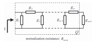
In the bandwidth of the filter, the input impedance is close to Rnorm.
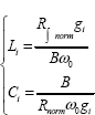
The values of the elements in the case of a bandpass structure are obtained from denormalization relations:

The resistance value depends on the load resistance value as well as on the value of gn+1. We may come across two cases depending on whether the filter’s last element is in series or parallel:
– series-element ![]()
– parallel-element ![]()
In the instances where we use Butterworth and ...
Get Design of Microwave Active Devices now with the O’Reilly learning platform.
O’Reilly members experience books, live events, courses curated by job role, and more from O’Reilly and nearly 200 top publishers.

