Color Plates
Figure 6.28 Temporal false colouring. Images taken at different times are assigned to different channels, with the resultant output showing coloured regions where there are temporal differences.
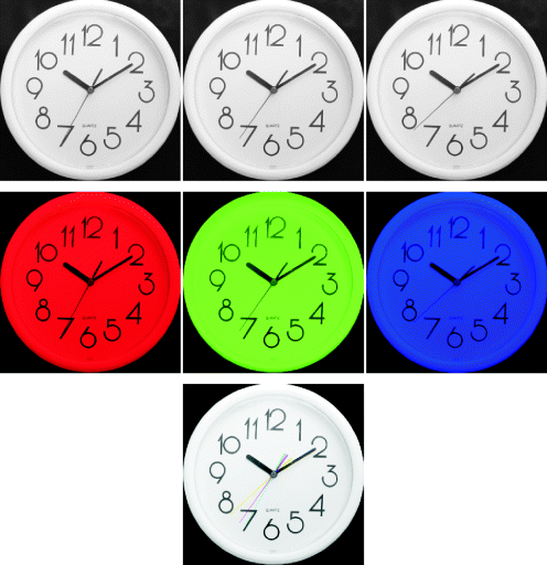
Figure 6.29 Pseudocolour or false colour mapping using lookup tables.
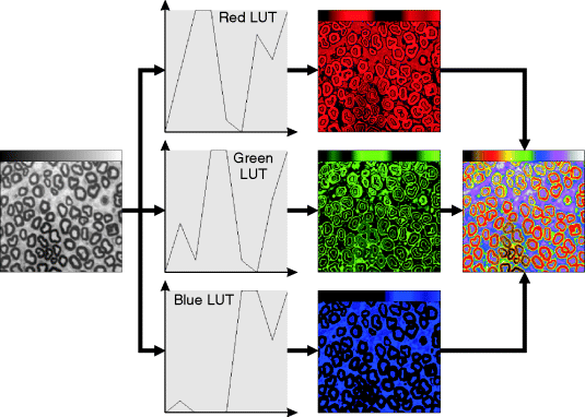
Figure 6.30 RGB colour space. Top left: combining red, green and blue primary colours; bottom: the red, green and blue components of the colour image on the top right.
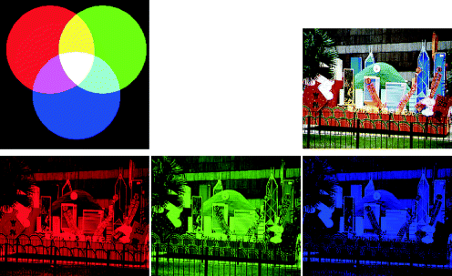
Figure 6.32 CMY colour space. Top left: combining yellow, magenta and cyan secondary colours; bottom: the yellow, magenta and cyan components of the colour image on the top right.
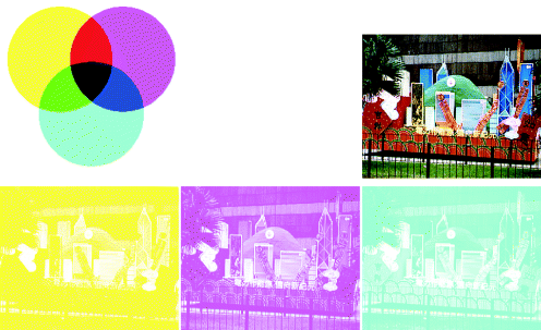
Figure 6.34 YCbCr colour space. Top left: the Cb–Cr colour plane at mid luminance; bottom: the luminance and chrominance components of the colour image on the top right.
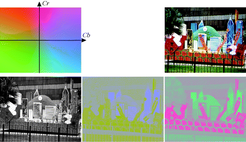
Figure 6.36 HSVand HLS colour spaces. Left: the HSV cone; centre: the HLS bi-cone; right: the hue colour wheel.
Figure 6.37 HSVand HLS colour spaces. Top left: HSV hue colour wheel, with saturation ...

