Appendix B Upwind Schemes
The first-order upwind scheme has been described in Chapter 4, Section 4.2.3. Here, we concentrate on the formulation of the second-order upwind and third-order QUICK schemes as illustrated below. As an improvement to the first-order upwind scheme, the idea is to incorporate additional variables located at the neighboring grid nodal points indicated by the properties at points WW and EE as shown in Fig. B.1 in order to evaluate the interface values at the cell faces of w and e.
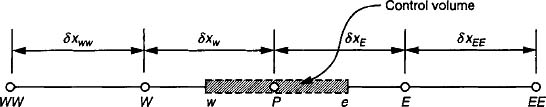
FIGURE B.1 A schematic representation of a control volume around a node P in a one-dimensional domain with surrounding grid nodal points of ...
Get Computational Fluid Dynamics now with the O’Reilly learning platform.
O’Reilly members experience books, live events, courses curated by job role, and more from O’Reilly and nearly 200 top publishers.

