The JFET as an Amplifier
31 Chapter 3 discussed the JFET in problems 28231, and Chapter 4 discussed the JFET in problems 37241. You may want to review these problems before answering the questions in this problem. Figure 8.30 shows a typical biasing circuit for a JFET.
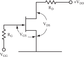
32 You can use a JFET to amplify AC signals by biasing the JFET with a gate to source voltage about halfway between the ON and OFF states. You can find the drain current that flows in a JFET biased to a particular VGS by using the following equation for the transfer curve:

In this equation, ...
Get Complete Electronics Self-Teaching Guide with Projects now with the O’Reilly learning platform.
O’Reilly members experience books, live events, courses curated by job role, and more from O’Reilly and nearly 200 top publishers.

