The Emitter Follower
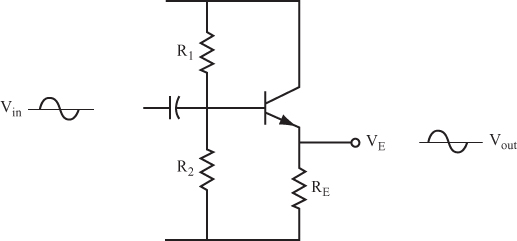
23 Figure 8.23 shows another type of amplifier circuit.
Question
How is the circuit shown in Figure 8.23 different from the amplifier circuit discussed in problems 11–18? _____
Answer
There is no collector resistor, and the output signal is taken from the emitter.
24 The circuit shown in Figure 8.23 is called an emitter follower amplifier. (In some cases, it is also called the common collector amplifier.)
The output signal has some interesting features:
- The peak-to-peak value of the output signal is almost the same as the input signal. In other words, the circuit gain is slightly less than 1; although in practice it is often considered to be 1.
- The output signal has the same phase as the input signal. It is not inverted; the output is simply considered to be the same as the input.
- The amplifier has a high input resistance. Therefore, it draws little current from the signal source.
- The amplifier has a low output resistance. Therefore, the signal at the emitter appears to be emanating from a battery or signal generator with a low internal resistance.
Questions
A. What is the voltage gain of an emitter follower amplifier? _____
B. Is the output signal inverted? _____
C. What is the input resistance of the emitter follower amplifier? _____
D. What is its output resistance? _____
Answers
A. 1
B. No
C. High
D. Low
25 The ...
Get Complete Electronics Self-Teaching Guide with Projects now with the O’Reilly learning platform.
O’Reilly members experience books, live events, courses curated by job role, and more from O’Reilly and nearly 200 top publishers.

