Phase Shift for an RL Circuit
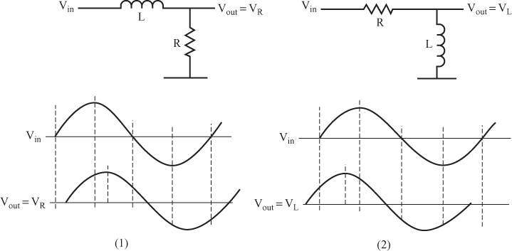
34 Filter circuits that use inductors (such as those shown in Figure 6.51) produce a phase shift in the output signal, just as filter circuits containing capacitors do. You can see the shifts for the circuits shown in Figure 6.51 by comparing the input and output waveforms shown below the circuit diagrams.
Question
In which circuit does the output voltage lead the input voltage? _____
In graph (1), the output voltage lags the input voltage, and in graph (2), the output voltage leads.
35 Figure 6.52 shows a vector diagram for both the circuits shown in Figure 6.51. The current through the inductor lags the voltage across the inductor by 90 degrees.
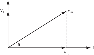
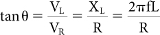
The phase angle is easily found:
Question
Calculate the phase angle for the circuit discussed in problem 30. _____
45 degrees
36 Refer to the circuit discussed in problem 31.
Question
Calculate the phase angle. _____
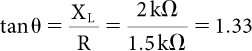
Therefore, θ = 53.1 degrees.
Get Complete Electronics Self-Teaching Guide with Projects now with the O’Reilly learning platform.
O’Reilly members experience books, live events, courses curated by job role, and more from O’Reilly and nearly 200 top publishers.

