Resistor and Capacitor in Parallel
26 The circuit shown in Figure 6.32 is a common variation on the low-pass filter circuit introduced in problem 15.
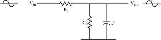
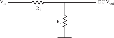
Because a DC signal will not pass through the capacitor, this circuit functions like the circuit shown in Figure 6.33 for DC input signals.
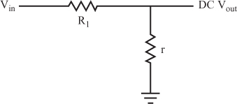
An AC signal will pass through both the capacitor and R2. You can treat the circuit as if it had a resistor with a value of r (where r is the parallel equivalent of R2 and XC) in place of the parallel capacitor and resistor. This is shown in Figure 6.34.
Calculating the exact parallel equivalent (r) is complicated and beyond the scope of this book. However, to demonstrate the usefulness of this circuit, you can make a major simplification. Consider a circuit where XC is only about one-tenth the value of R2 or less. This circuit has many practical applications, because it attenuates the AC and the DC differently.
The following example can help to clarify this. For the following circuit, calculate the AC and DC output voltages separately.
For the circuit shown in Figure 6.35, you can calculate the AC and DC output voltages separately by following the steps ...
Get Complete Electronics Self-Teaching Guide with Projects now with the O’Reilly learning platform.
O’Reilly members experience books, live events, courses curated by job role, and more from O’Reilly and nearly 200 top publishers.

