Switching the JFET
37 The use of the junction field effect transistor (JFET) as a switch is discussed in the next few problems. You may want to review problems 28 through 31 in Chapter 3 where this book introduced the JFET.
The JFET is considered a “normally on” device, which means that with 0 volts applied to the input terminal (called the gate), it is ON, and current can flow through the transistor. When you apply a voltage to the gate, the device conducts less current because the resistance of the drain to the source channel increases. At some point, as the voltage increases, the value of the resistance in the channel becomes so high that the device “cuts off” the flow of current.
Objective
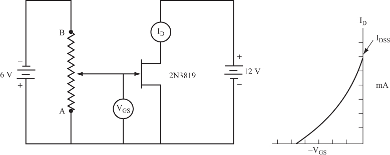
The objective of this project is to determine the drain current that flows when a JFET is fully ON, and the gate voltage needed to fully shut the JFET OFF, using the circuit shown in Figure 4.22.
General Instructions
After the circuit is set up, change ...
Get Complete Electronics Self-Teaching Guide with Projects now with the O’Reilly learning platform.
O’Reilly members experience books, live events, courses curated by job role, and more from O’Reilly and nearly 200 top publishers.

