The Three-Transistor Switch
24 The circuit shown in Figure 4.19 uses three transistors to switch a load on and off. In this circuit, Q1 is used to turn Q2 ON and OFF, and Q2 is used to turn Q3 ON and OFF. The calculations are similar to those you performed in the last few problems, but a few additional steps are required to deal with the third transistor. Use the circuit diagram in Figure 4.19 to determine the answers to the following questions.
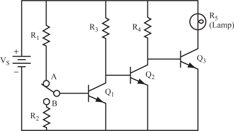
Assume that the switch is in position A.
25 Now use the same circuit as in problem 24.
Assume that the switch is in position B.
Get Complete Electronics Self-Teaching Guide with Projects now with the O’Reilly learning platform.
O’Reilly members experience books, live events, courses curated by job role, and more from O’Reilly and nearly 200 top publishers.

