Working with Paths
Drawing lines is the most basic function you can perform with
Cocoa’s drawing classes. The Application Kit
encapsulates the low-level,
Quartz path-based drawing API in the
NSBezierPath
class. Minimally,
NSBezierPath lets you draw straight lines and
Bezier paths, and using this functionality, you can construct any
shape you like.
Tip
Bezier curves, or paths, are curved lines based on the mathematics of third-degree polynomials. Because Bezier paths are based on equations, they are resolution-independent and can be scaled to any size without the loss of detail or quality generally experienced with bitmapped graphics.
Drawing with NSBezierPath is in some respects similar to
drawing on a sheet of paper with a pencil. Before you can draw a
line, you have to place the pencil lead at a point on the page.
Drawing a line requires moving the pencil from one point to another.
To draw a disjointed line, you pick up the pencil tip from the paper
and move it to another location. You might then complete a diagram by
drawing a line back to the first point. These actions are reflected
in the following NSBezierPath methods, used to
construct a path:
moveToPoint:lineToPoint:curveToPoint:controlPoint1:controlPoint2:closePath
The arguments to the first three methods are all of type
NSPoint, a C structure that encapsulates a
coordinate pair. Example 4-1 shows the
struct declaration for NSPoint.
At any time, there is a current point. The method
moveToPoint: moves the current point to the
specified point. The methods lineToPoint: and
curveToPoint: controlPoint1:controlPoint2: both
extend a path from the current point.
Tip
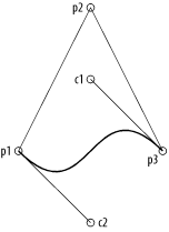
Bezier curves (a subset of Bezier paths) are defined by two endpoints and two control points. The line segment connecting an end point to its control point is tangent to the curve at the end point and defines the path’s direction. Figure 4-4, later in this chapter, shows the lines connecting each endpoint to their associated control point for the curve that makes up the bottom of the triangle.
Drawing
with NSBezierPaths is fundamentally different from
drawing with a pencil in that constructing a path is not the same as
drawing a path. You can think of a path as an abstract representation
that can be rendered into one, or many, views.
NSBezierPath provides two methods to render a
path: stroke, and fill.
stroke draws the outline of the path, while the
fill
method fills the interior of the path
with a color or pattern.
To illustrate this, consider Example 4-2, which draws the image shown in Figure 4-3.
// The three vertices of a triangleNSPoint p1 = NSMakePoint(100, 100); NSPoint p2 = NSMakePoint(200, 300); NSPoint p3 = NSMakePoint(300, 100);// Control pointsNSPoint c1 = NSMakePoint(200, 200); NSPoint c2 = NSMakePoint(200, 0);// Constructing the path for the triangleNSBezierPath *bp = [NSBezierPath bezierPath]; [bp moveToPoint:p1]; [bp lineToPoint:p2]; [bp lineToPoint:p3]; [bp curveToPoint:p1 controlPoint1:c1 controlPoint2:c2]; [bp closePath]; [bp stroke];
For simple drawing, such as constructing rectangles or ellipses,
NSBezierPath has two methods:
bezierPathWithRect: and
bezierPathWithOvalInRect:. Both methods take an
NSRect as an argument. In the first method, the
NSRect defines the constructed rectangle. In the
second method, the specified rectangle determines the boundary of the
ellipse. In addition to these two constructors,
appendBezierPathWithOvalInRect: and
appendBezierPathWithRect: add an ellipse or
rectangle to an existing path.
You can also construct arcs with the following three methods:
appendBezierPathWithArcWithCenter:radius:startAngle:endAngle:clockwise:appendBezierPathWithArcWithCenter:radius:startAngle:endAngle:appendBezierPathWithArcFromPoint:toPoint:radius:
These methods measure angles in degrees. The first
draws an arc centered at the specified center point with a given
radius. The arc extends from startAngle: to
endAngle:, clockwise or counterclockwise,
depending on the value of the clockwise argument. The second method
is a wrapper around the first, where clockwise: is
NO.
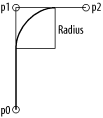
The third method,
appendBezierPathWithArcFromPoint:toPoint:radius:,
draws an arc from a circle that is inscribed within the angle
specified by the current point in a path and the two points specified
in the method. The parameter radius: specifies the
radius of the circle used to build the arc. This method is more
complicated than the other two, so it is illustrated by example.
Example 4-3 shows the code used to build the path in
Figure 4-4, shown with a bold line.
Drawing to Views
To draw in a given view, you must first lock
focus
on the view by sending it a
lockFocus
message. Quartz interprets all
subsequent drawing commands in the context of that view. Once the
drawing is done, balance the lockFocus with a
matching unlockFocus to the same view.
Custom drawing is implemented in a subclass of
NSView. When subclassing
NSView, all drawing code is called from an
overridden drawRect: method. This method of
NSView does nothing by default, but the
NSView graphics system is set up to automatically
invoke this method at the appropriate times.
While drawRect: does the drawing work, it should
never be invoked directly. Instead, to force an immediate redraw of a
view, you can send a display message to the view.
This causes the receiver to lock its focus, invoke
drawRect:, and then unlock its focus before
returning control to the caller. To this end,
display is functionally similar to the
implementation shown in Example 4-4.
- (void)display
{
  [self lockFocus];
  [self drawRect:[self bounds]];
  [self unlockFocus];
}
However, display is still not the interface you
usually use to tell a view to redraw its contents. A better method of
redrawing tells the view that the contents have changed and lets the
view redraw itself the next time through the run loop. You do this by
sending the view a setNeedsDisplay: message, with
the argument YES to indicate that the view should
invoke display in the next run loop pass. If you
want to cancel a drawing request, invoke this method passing
NO. This allows Quartz to decide the proper time
to redraw the contents of a view.
In some circumstances it may be more efficient still to send the view
a setNeedsDisplayInRect: message, where the
argument is a “dirty” area that
needs to be updated. The display system can then determine what
rectangle to pass as the argument to a view’s
drawRect:. In your drawing code, you then ensure
that you only update parts of the view that need to be refreshed.
Other methods used to cause view updates include:
- (void)displayIfNeeded;
|
- (void)displayIfNeededIgnoringOpacity;
|
- (void)displayRect:(NSRect)rect;
|
- (void)displayIfNeededInRect:(NSRect)rect;
|
- (void)displayRectIgnoringOpacity:(NSRect)rect;
|
- (void)displayIfNeededInRectIgnoringOpacity:(NSRect)rect;
|
Line Attributes
NSBezierPath
lets you change
several
path-rendering options, such as the line thickness, join style, dash
count, miter limit, cap style, and winding rules. You can change a
path’s attributes with a class method or an instance
method. The instance method changes the attributes of only the
receiving instance, while the class method changes the default
attribute for all instances in the graphics context.
For example, to change the width of a line, use either
setLineWidth: or
setDefaultLineWidth:. The first changes the line
width of the instance to which you send that particular method, while
the second class method sets the line width in the graphics context
that applies to subsequent renderings of any instance of
NSBezierPath.
NSBezierPath provides methods for changing the
following attributes:
You can change any of these attributes for a single instance or for the graphics context, as shown earlier.
Path flatness
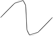
Flatness is one attribute that can be set for a curve. A path’s flatness indicates to the rendering engine how accurately it should reproduce the curve; that is, the flatness is a metric of the curve’s granularity or resolution as it is rendered. A higher flatness value corresponds to a rougher curve, which can be rendered more quickly; a lower value corresponds to a smoother curve, which comes at the expense of rendering time. Figure 4-5 shows a curve that is stroked with the default flatness of 0.6, and again with a larger flatness of 100 using a thicker line. Example 4-5 shows the code you need to change the flatness.
Tip
How jagged a curve appears depends on the flatness and the absolute size of the curve. Endpoints of the curve in Figure 4-5 are 500 pixels apart; if the absolute size of the curve were 10 times as large, a flatness of 100 would create less dramatic jaggedness.
Related to setting the flatness of a
rendered curve is the method
bezierPathByFlatteningPath. This method returns a
Bezier path that represents the receiver with all curves approximated
as a series of straight lines similar to how changing the flatness
renders the curve.
Line dashes and phase
The method
setLineDash:count:phase: takes three parameters to
define a dash pattern for a stroked Bezier path. The first argument
is a C array of floats that specifies the lengths
of alternating stroked and unstroked segments. The second argument
indicates the number of elements in the dash pattern array. The final
argument indicates where in the dash pattern drawing begins. Consider
the three dash patterns in Example 4-6 and the
resulting lines in Figure 4-6.
float pattern1[2] = {50.0, 25.0};
float pattern2[3] = {50.0, 25.0, 75.0};

// The top line in Figure 4-6
[aPath setLineDash:pattern1 count:2 phase:0];

// The middle line in Figure 4-6
[aPath setLineDash:pattern2 count:3 phase:0];

// Bottom line in Figure 4-6
[aPath setLineDash:pattern1 count:2 phase:25];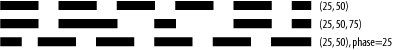
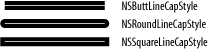
Line cap style
You can render Bezier paths with several
line cap styles, which are set using either
setLineCapStyle: or
setDefaultLineCapStyle:. The line cap style
NSButtLineCapStyle makes the ends of the rendered
line flush with the end of the path.
NSRoundLineCapStyle renders the line with a radius
equal to half the thickness of the line, centered at the end of the
path. Finally, NSSquareLineCapStyle extends the
line past the end of the path by a length equal to half of the line
width. The default line cap style is
NSButtLineCapStyle. Figure 4-7
shows various line cap styles on a path that is 200 pixels long and a
width of 30 pixels; the white line indicates the path to highlight
the position of the endpoints (which is critical when discussing the
differences between NSButtLineCapStyle and
NSSquareLineCapStyle).
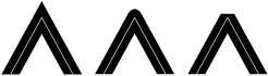
Line join styles
Another property of Bezier paths is the way
lines are joined. You can set this property for path objects with
setLineJoinStyle:, or set it for the graphics
context with setDefaultLineJoinStyle:. The default
line join style is NSMiterLineJoinStyle, in which
the outside edges of the lines are extended to a sharp point. You can
also create rounded and beveled line join styles using the constants
NSRoundLineJoinStyle and
NSBevelLineJoinStyle. Figure 4-8
shows examples of the three lines join styles.
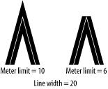
Miter limit
Miter join
styles have a special problem: the join appears as a spike when the
angle between the two joined lines is extraordinarily acute (since
the join is rendered by extending the outer line edges outward until
they meet). To prevent this problem, the graphics context has a
miter limit that defines a threshold for how
small an angle can be before the line join style is changed to a
bevel joint. The miter limit is the ratio of the miter length (the
diagonal length of the miter extension) to the line width; by
default, this is value is 10. To alter this value, use
NSBezierPath’s class method
setDefaultMiterLimit:, or the instance method
setMiterLimit:.
Figure 4-9 illustrates a small-angle joint. The joint with the miter join style is drawn with the default miter limit of 10, while the miter limit that produces the bevel joint is reduced to 6. In each example, the line thickness is 20 and the angle between the two lines is about 9.5 degrees.
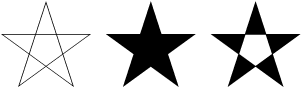
Winding rule
When filling a path, there is another graphics context characteristic to consider: the winding rule. For simple paths such as rectangles and circles, the region that should be filled is unambiguous. However, for complex paths, such as a star with many intersecting line segments, the area that should be filled is less clear. Thus, winding rules are used to determine which regions of a complex intersecting path should be filled.
The two winding rules are non-zero (the default) and even-odd . The even-odd winding rule works by taking a test point within the region and counting the number of times a ray extending from that point crosses the path. If the number of crossings is odd, then the point is considered “inside” the shape, and its region will be filled. If the number of crossing is even, then the point is considered “outside” the shape, and its enclosing region is not filled.
The non-zero winding rule counts crossings based on the direction of the crossed path. A ray extending from the test point increments its crossing count when it crosses a left-to-right path; it decrements its crossing count when crossing a right-to-left path. If the number of crossings is 1, then the point is “inside;” if the number of crossings is zero, then the point is “outside.” Figure 4-10 shows an example of these two winding rules at work.
Get Cocoa in a Nutshell now with the O’Reilly learning platform.
O’Reilly members experience books, live events, courses curated by job role, and more from O’Reilly and nearly 200 top publishers.

