Chapter 4. HiJack
What Is HiJack?
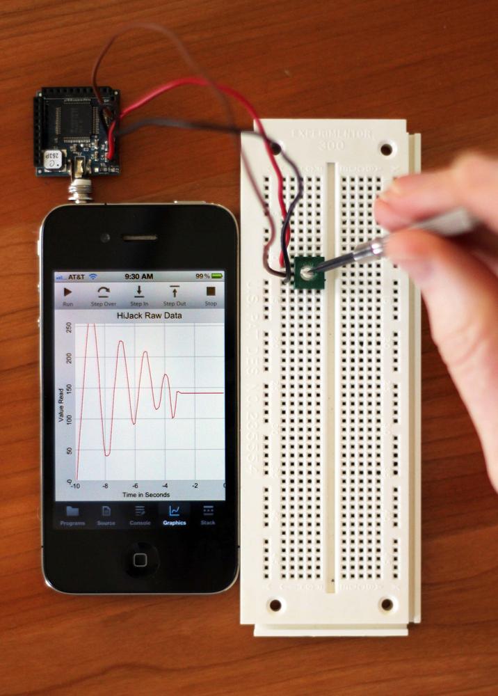
HiJack (shown in Figure 4-1) is a hardware device that plugs right into your iPhone, iPad, or iPod headphone jack. It’s the only wired technology that can connect to iOS devices that isn’t controlled by Apple’s MFi program. This means it is also the only wired technology for which Apple will approve apps for the App Store without going through the MFi program.
The current HiJack firmware supports an eight-bit A–D converter that takes an input of 0–2.75 volts. In this chapter we’ll look at how to hook up the HiJack hardware and write a simple program to access data. The next chapter looks at a practical application.
In the programming world, it’s traditional to start off with a new computer language by writing a simple program that prints “Hello world!” This convention started with Brian Kernighan, who wrote the first hello world program in a tutorial for the B programming language in 1972. With over 40 years of tradition behind us, we’ll start our exploration of the HiJack hardware with a simple program to read the data, and a simple hardware project to provide that data—hello world, hardware style. We’ll call our program “Hello HiJack.”
One of the challenging things about interfacing hardware to a computer is that it involves at least two distinct disciplines: electrical engineering and programming. If you are reading this book, you’re probably at least conversant with one of these fields, but very few people are expert in both. Because of that, I’ll provide a lot more background in programming than the programmers need, and more background in electronics than the electrical engineers need. I’m sure you’re good at skimming by now, so feel free to skip over the sections you already know.
Building the Sensor
Table 4-1 provides the list of parts you’ll need for this project.
| Part | Description |
This includes everything you see in Figure 4-2. | |
Potentiometer | Anything in your parts bin will do. I used a 10KΩ potentiometer. |
Breadboard | Breadboards are used to prototype electrical circuits. The white plastic part with all the holes that you saw back in Figure 4-1 is a popular size and style. We will use breadboards for many projects in this book. It’s not required, but it makes life a lot easier. |
Power supply | All iPads and all iPhones beginning with the iPhone 4S will require an external power source. This can be as simple as a 3-volt battery. A small, mobile power supply is shown in External Power for HiJack. |
Let’s start with the hardware itself. HiJack was developed at the University of Michigan for the purpose of creating cubic-inch sensor peripherals for mobile phones like the iPhone. It works just as well from the iPad. The whole idea is to give you a hardware platform that you can build on. You can buy the hardware from Seeed Studio, which sells the raw hardware, a development pack, and a few odd components. I got the development pack, shown in Figure 4-2. It comes with the actual HiJack device, which is the green board with the headphone connection, along with a few other goodies.
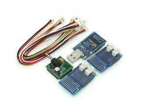
The most important extra is the board with the USB plug; this is used to download new firmware as it becomes available. Be warned, though: the software to install firmware on the HiJack board only runs on Windows and is fairly temperamental. You won’t have to do this right away—the HiJack device is preloaded with the current firmware—but if you ever want to update the firmware, a Windows computer is required.
The two blue boards are prototyping boards that are designed to plug snugly into the HiJack board. We’ll make use of one of those later in the chapter. The various wiring harnesses are used to connect the prototyping boards to other devices, notably the prebuilt sensors in the Grove modular toolset. The Grove components include a collection of sensors, some of which work with HiJack right out of the box. They are also available from Seeed Studio. We’ll be using one of them in the next chapter, so skip ahead and take a look at that before placing an order.
With a HiJack board in hand, the first thing we need to do is build a sensor. Ours will be about as simple as they come: we’ll use a potentiometer (variable resistor) to provide a voltage we can change by varying the resistance. You can pick up potentiometers from pretty much anyplace that sells electronics components. The specific resistance doesn’t matter, either. I used a tiny little 10KΩ (10,000 ohm) trim pot I had lying around in a parts bin.
The idea behind this sensor is to divide the voltage supplied by the HiJack device. Resistors in series divide an input voltage. Figure 4-3 shows a diagram of the circuit we’ll be building. Purists will notice that I showed two separate resistors rather than a potentiometer. Electrically, they are the same thing as long as the potentiometer is not being adjusted, though, and it makes the following discussion a little easier.
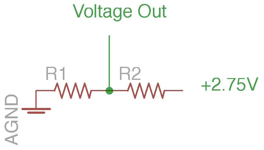
The two lines labeled AGND at the left are the ground connection, abbreviated GND on the Seeed Studio documentation. This is the negative voltage side of the circuit. The other side, marked +2.75V, is the positive power supplied by the HiJack device. This pin is marked VCC on the Seeed Studio documentation. Our circuit will connect up to these two pins to draw power across the potentiometer.
A potentiometer is essentially, and sometimes literally, a resistive bar that uses a slider of some sort that covers the resistor. The bar is connected to a third wire. Sliding the bar changes the resistance to either side, dividing it into two parts that always add up to the total resistance in the device. The voltage output from the ground connection to the center wire of the resistor will be:

Here, Vin is the 2.75 volts supplied by HiJack, and R1 and R2 vary as you adjust the potentiometer. Anything that detects the voltage from the ground connection to Voltage Out will see the voltage vary from 0 to 2.75 volts as the potentiometer is turned. That’s exactly what the HiJack hardware will measure.
On the other end of the circuit sits the HiJack device itself. The top of the HiJack device has three female headers that provide 10 wiring connections each. Figure 4-4 shows the pin out, from a larger diagram available at the Seeed Studio site.
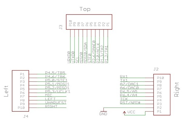
The connections we’re interested in are on the right bar. We’ve already talked about GND and VCC; those pins provide the 2.75-volt power source we are using. The data input line is A6/DAC0. That’s the pin we need to connect to the center pole on the potentiometer. Following the convention of black wires for ground and red for positive in DC circuits, and using a brown wire because I had one handy in my parts box, Figure 4-5 shows a closeup of the connections on the HiJack device.
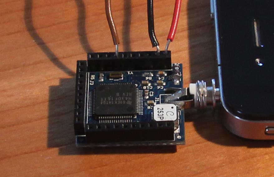
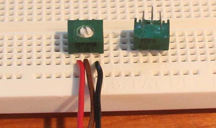
Potentiometers have three pins. In general, the center pin is the one we want to hook up to A6/DAC0, and GND and VCC can be connected to either of the two remaining pins. Figure 4-6 shows what it looks like in my circuit, with a second, identical potentiometer upside down beside the one I used so you can see the pins coming out of the bottom. I used a breadboard for the connections, but that’s because I had one lying around. Anything that will securely mount the wires to the potentiometer and let you easily adjust the resistance will work just fine.
External Power for HiJack
Table 4-2 provides the parts list for the external power supply.
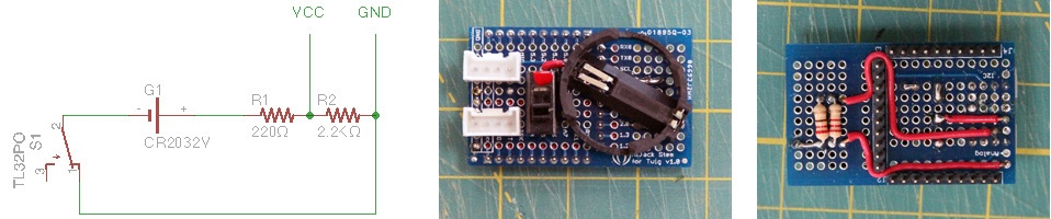
HiJack was designed to draw power from the audio output of the headphone port, a clever design feature that started to fail when Apple reduced the power output beginning with the iPhone 4S and on all models of the iPad. It’s easy enough to correct this problem by supplying 2.75V to VCC on the HiJack chip, as shown in Figure 4-7. The designers strongly cautioned me, however, not to exceed 3V.
Warning: Don’t exceed 3V!
Providing more than 3V from an external power source can damage the HiJack device. Since most 3V batteries will actually supply 3.3V when new, I was overly cautious and dropped the voltage using a resistive circuit very much like the one in the Hello World circuit. If you supply external power to a HiJack, please limit the voltage using a simple circuit like this one or, better still, a regulated power supply.
One way to supply the power is with a coin cell battery attached to one of the prototyping boards that comes with the HiJack development kit, as shown in Figure 4-8.
You can get really fancy or keep it simple. Due to the limited working space, I chose simplicity, using a 220Ω resistor and a 2,200Ω resistor to drop the voltage from 3.3V to 3V and a switch to turn the power on or off. Mounting the circuit on one of the prototyping boards makes for a very convenient, portable package that works very well with the Grove sensors. It’s easy to tap A6, VCC, and GND from the connector on top of the prototyping board using one of the cables that comes with the HiJack Development Pack. The black and red wires are ground and +2.75V, respectively, and the yellow wire is A6.
Hello HiJack
With all of that hooked up, it’s time to write our program (shown running in Figure 4-9) to display what’s happening.
Run techBASIC from your iPhone or iPad, tap the New button to create a new program, and enter “Hello HiJack” as the program name. Tap the Source screen to get the keyboard and enter this program:
WHILE 1System.clearConsole
PRINT HiJack.receive
System.wait(0.5)
WEND
Here’s how the program works:
-
The
WHILEandWENDlines form a loop that will continue as long as the expression in theWHILEstatement is nonzero. One will be nonzero for a really long time, so the loop will go forever. The only way to stop this program will be to press the Stop button that will show up at the top of the screen when the program starts running.-
System.clearConsoleclears any text from the console, where text input and output appear.-
The
PRINTstatement then prints a two-dimensional array to the screen. It gets that array from the HiJack hardware--HiJack.receiveis a function that returns an array where the first element is a value between 0 and 255, with lower numbers when the voltage is low and higher numbers when it is high. The second value on the line is a timestamp. The timestamp may not seem to change much, but it’s a large number whose most significant digits change slowly.-
System.wait(0.5)pauses for a moment so we get a chance to read the screen without too much flicker. The parameter tells the call how long to pause, in this case for half a second.
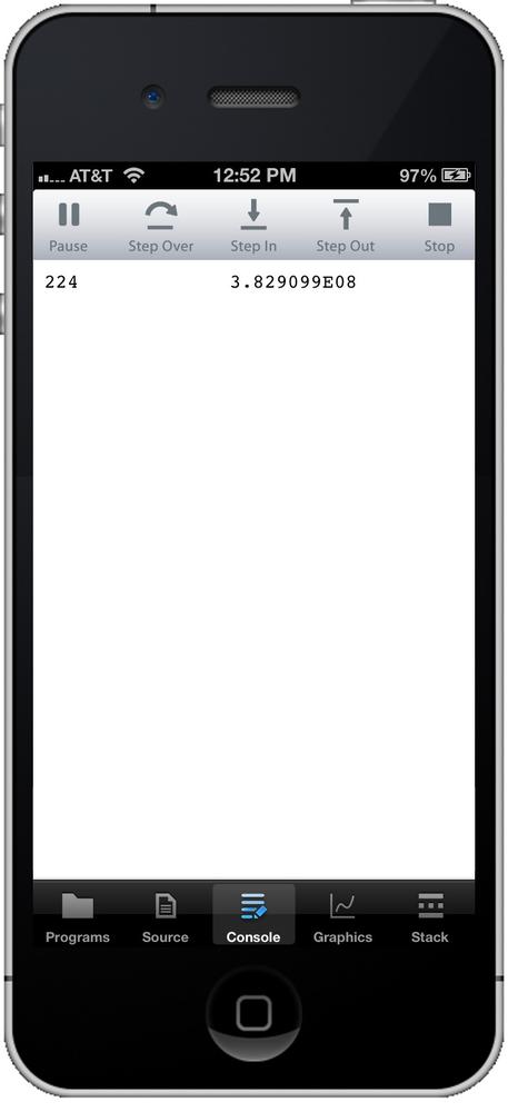
After typing in the program, plug the HiJack hardware into the headphone jack on your iPhone. Tap the Programs button at the bottom of the screen, then tap the name of the program. techBASIC will change the display to the console, where you should see a number that occasionally changes. The output will look something like this:
71 3.804955E08
After a second or two, the first number will settle down to a single value, or perhaps flick back and forth between two values. Adjust the potentiometer, and you’ll see the number change. Just a few more steps, and you’ll be building RoboCop!
When Things Go Wrong
OK, not so fast. Did it work? If not, there are two places for things to go wrong: the software or the hardware.
If there is a problem with the software, techBASIC may say so. Check to make sure the program is exactly the one typed above. Letter case is not important, but spaces and line breaks can be. Make sure there are five lines, and that there are spaces between the words where shown, and no extra spaces inserted. clear Console is not the same as clearConsole! Also, look at the error messages from techBASIC. They will usually pinpoint the problem, and even if they don’t, the real problem will be close by.
If the program is running and printing numbers, but the numbers seem to jump around randomly, you probably don’t have a good connection or the HiJack device does not have enough power. Check to make sure the HiJack hardware is plugged all the way into the headphone port. The metal disk on the washer does not fit flush against the case, so don’t push too hard. If you are using an iPod Touch, you may also need to twist the jack around a bit.
Power can be a real problem with the HiJack device. There is no battery—it is getting its power from an audio tone generated by the iPhone. Make sure the volume is turned all the way up. Also, Apple lowered the power output for the headphones starting with the iPhone 4S and with all models of the iPad. You’ll need an external power source for the later model devices (refer back to External Power for HiJack ). With an external power supply, HiJack doesn’t need to draw power from the sound coming out of the headphone port, so you can turn it down. Leaving the volume turned up won’t do any harm, but it will drain the iPhone’s battery a little faster.
The last potential source of trouble is the HiJack hardware or the circuit. Check it carefully to make sure the right wires are connected to the right places, and that the wires are making a good electrical contact.
A Better HiJack Program
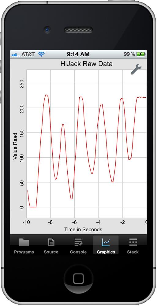
While that first little program worked, it’s not the most exciting program in the world. Wouldn’t it be nicer to have something like an oscilloscope trace, like the ones from the programs in the first three chapters that access the internal sensors? It’s actually not that hard. In fact, let’s do that now.
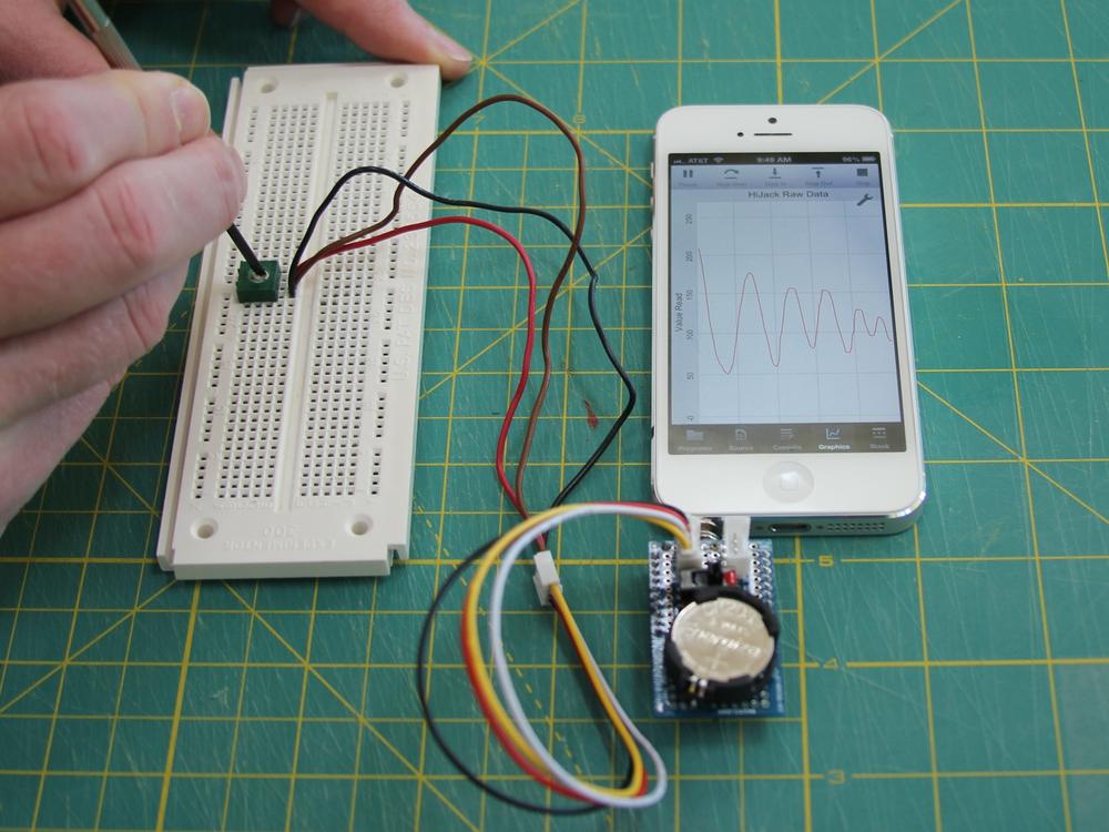
Our goal is a program that plots results like those in Figure 4-10. We’ll plot 10 seconds’ worth of data, collecting a data point every 0.1 seconds, for a total of 100 data points plotted at any one time. The newest data will always appear at the right, at time=0, and older data will be scrolled to the left, with time getting more and more negative until the point falls off of the display.
Let’s take a look at the code. I’ll show the complete program first, then we’ll walk through it line by line.
Note
This program is included in techBASIC and techBASIC Sampler. Look for the app called HiJack in the O’Reilly Books folder.
The finished program looks like this:
! Shows a running plot of HiJack
! input for the last 10 seconds
! in 0.1-second intervals.
!
! Initialize the display with the
! value set to 0.
DIM value(100, 2)
FOR t = 1 TO 100
  value(t, 1) = (t - 100)/10.0
NEXT

! Initialize the plot and show
! it.
DIM p as Plot, ph as PlotPoint
p = Graphics.newPlot
p.setTitle("HiJack Raw Data")
p.setXAxisLabel("Time in Seconds")
p.setYAxisLabel("Value Read")
p.showGrid(1)
p.setGridColor(0.8, 0.8, 0.8)

ph = p.newPlot(value)
ph.setColor(1, 0, 0)
ph.setPointColor(1, 0, 0)

! Set the plot range and
! domain. This must be done
! after adding the first
! PlotPoint, since that also
! sets the range and domain.
p.setView(-10, 0, 0, 255, 0)

system.showGraphics

! Loop continuously, collecting
! HiJack data and updating the
! plot.
DIM time AS double
time = System.ticks - 10.0
WHILE 1
  ! Wait for 0.1 seconds to
  ! elapse.
  WHILE System.ticks < time + 10.1
  WEND
  time = time + 0.1

  ! Get and plot one data point.
  h = HiJack.receive
  FOR i = 1 TO 99
    value(i, 2) = value(i + 1, 2)
  NEXT
  value(100, 2) = h(1)
  ph.setPoints(value)
  Graphics.repaint
WEND
OK, that’s not too long, as programs go. It’s just 55 lines, and a lot of them are comments. Let’s see what it does. Here’s the first chunk:
! Shows a running plot of HiJack
! input for the last 10 seconds
! in 0.1-second intervals.
!
! Initialize the display with the
! value set to 0.
DIM value(100, 2)
FOR t = 1 TO 100
  value(t, 1) = (t - 100)/10.0
NEXT
This first chunk of code makes some introductory comments, then sets up an array to hold the values we will eventually read from the HiJack hardware. The array value will hold up to 100 values. It’s a two-dimensional array because we will need to tell techBASIC both the x and y values for each point to plot. The x values are the timeline, which doesn’t change, so we use a FOR loop to fill in these values. Our intent is to collect one point every 0.1 seconds and display 10 seconds’ worth of data, so we fill in the x values with values ranging from -9.9 to 0. We can safely leave the y values unchanged, since BASIC initializes new variables to 0, and that will work fine for our purposes. All of this will sound very familiar if you have already worked through the first three chapters.
! Initialize the plot and show
! it.
DIM p as Plot, ph as PlotPoint
Next, we need to create a plot. The DIM statement sets up two variables, one to hold the Plot class that displays the plot itself and another for the PlotPoint class, which contains the actual points to plot.
p = Graphics.newPlot
p.setTitle("HiJack Raw Data")
p.setXAxisLabel("Time in Seconds")
p.setYAxisLabel("Value Read")
p.showGrid(1)
p.setGridColor(0.8, 0.8, 0.8)
The first line of the next block creates the plot itself. Think of this as the background, including the titles, axes, and so forth. The setTitle method sets the title at the top of the plot, while the next two lines set the axis labels. showGrid turns on the grid lines that appear behind the plot line; without this call, the background is blank. Finally, we set the grid color to a light gray. Like almost all techBASIC calls that take a color, setGridColor takes three parameters, one each for the intensity of the red, green, and blue colors, in that order. The valid values range from 0.0 to 1.0, with 0.0 being black and 1.0 being the full intensity for that color. A few calls have a fourth number for the alpha channel, which tells how transparent a color is. That lets you draw something over a background and, to the degree specified by the alpha value, see through the new color to whatever lies behind it. Check out the RGB color model article on Wikipedia if you would like to know more about how RGB color works on a computer.
ph = p.newPlot(value)
ph.setColor(1, 0, 0)
ph.setPointColor(1, 0, 0)
The next step is to set up the PlotPoint class that actually draws the line across the plot. The newPlot method creates a new instance of the class and adds it to the plot we just created. We then set the color for both the line and the points where the data is actually plotted to red. There are other calls in the PlotPoint class that control the shape of the points and line; you can use those to customize your version of the program.
! Set the plot range and
! domain. This must be done
! after adding the first
! PlotPoint, since that also
! sets the range and domain.
p.setView(-10, 0, 0, 255, 0)
HiJack always returns a value from 0 to 255, and we know the x-axis will show times from –10 to 0 seconds, so next we set the axis to show exactly those values. Without this call, techBASIC will default to showing 0 to 10 along the x-axis and roughly –5 to 5 along the y-axis. We can always change what we are looking at with some swipe and pinch gestures, but this saves us the trouble.
system.showGraphics
Now that things are set up, we tell techBASIC to switch to the graphics display. Again, we could have done this with a tap on the Graphics button, but this saves us the trouble.
! Loop continuously, collecting
! HiJack data and updating the
! plot.
DIM time AS double
time = System.ticks - 10.0
HiJack can report data at various rates, up to a little more than 100 points per second. The default rate in techBASIC is about 40 values per second, which is more than we need. These lines set up a timestamp we will use to tell when 0.1 seconds have elapsed. Each time that happens, we’ll grab a new point from the HiJack hardware and add it to our plot.
WHILE 1
Just like the first program, this program will loop until you manually end it with the Stop button.
  ! Wait for 0.1 seconds to
  ! elapse.
  WHILE System.ticks < time + 10.1
  WEND
  time = time + 0.1
Here is where we wait for 0.1 seconds to elapse. The WHILE loop waits until the system clock reports a time 10.1 seconds past the original time we recorded before the loop started. We then add 0.1 to this time so the next time through, this timer loop will wait until 10.2 seconds have gone by, and so forth.
  ! Get and plot one data point.
  h = HiJack.receive
This is all it takes to actually read the HiJack hardware. A value from 0 to 255 is stuffed into the variable h.
  FOR i = 1 TO 99
    value(i, 2) = value(i + 1, 2)
  NEXT
This loop shifts the 99 most recent points in the value array one index lower, which will cause them to be drawn one point to the left on the plot. Remember, the time is preset and is not being shifted, so this essentially makes each point 0.1 seconds older on the plot. The first time through, this is just copying a bunch of zeros, but after 10 seconds, all of the values are older values read from the HiJack hardware.
value(100, 2) = h(1)
The new point goes in the last spot in the plot. We pull off the first element of the array, which is the HiJack data, and ignore the second, which contains a timestamp we don’t need in this program.
  ph.setPoints(value)
  Graphics.repaint
This tells the PlotPoint object we created and stored in ph to use a new set of points. Next we repaint the graphics screen, showing the new information on the plot.
WEND
Finally, we go back to the WHILE statement and do it all again.
Try out the finished program with HiJack, as shown in Figure 4-11. You should be able to see exactly where the potentiometer is set, and watch the change as you adjust it. This program will work with all of your HiJack projects, although you will probably develop custom programs for specific sensors and uses.
For More Information
You can find out more about HiJack at the University of Michigan’s HiJack page and at the wiki on the Seeed Studio site. The Seeed Studio website also has information about other hardware projects you can build, downloads for the software to update the firmware on the HiJack, and the latest version of the firmware.
Get Building iPhone and iPad Electronic Projects now with the O’Reilly learning platform.
O’Reilly members experience books, live events, courses curated by job role, and more from O’Reilly and nearly 200 top publishers.

