Chapter 4. Reimagining BGP Configuration
This chapter shows how router configuration can be reduced by completely eliminating interface IP addresses and specifying the remote-as of each neighbor. Both of these improvements will make configuring a BGP router in the data center a snap, and automation a breeze.
In Chapter 3, we showed how you could eliminate IP address usage from the BGP configuration. However, the operator still needs to configure IP addresses on the interfaces for BGP peering. Because these interface addresses are never used for anything but BGP configuration and their information is never propagated via BGP, their configuration is a meaningless holdover from the service provider world in the data center. Another issue mentioned toward the end of Chapter 3 about automating the configuration is the need to know the remote-as of the peer.
After we eliminate these two requirements, we’re left with a configuration that is homogeneous and duplication-free across the nodes, with the only node-specific content being the node’s ASN and its router-id. In other words, the configuration is very automation friendly, and simple.
To achieve these goals, we’ll need to understand a topic almost as old as routing: unnumbered interfaces, and how we adapt this construct to BGP.
The Need for Interface IP Addresses and remote-as
Because BGP runs on TCP/IP, it needs an IP address to create a connection. How can we identify this remote node’s address while at the same time not allocating any IP addresses on interfaces? Answering this question will involve understanding a lesser-known RFC and the stateless configuration tools provided by IPv6. It also involves understanding the real heart of routing.
The second problem is that every BGP configuration relies on knowing the remote ASN. But this ASN is really required for only one thing: to identify whether the session is governed by the rules of internal BGP (iBGP) or external BGP (eBGP).
The Numbers on Numbered Interfaces
Is configuring IP addresses on an interface really that big of a deal? How many of them can there be anyway?
Consider a simple two-tier Clos with 4 spines and 32 leaves—a fairly common network. Each spine has 32 links, one to each leaf, and there are 4 spines. This requires 4 * 32 * 2 = 256 IP addresses (4 spines * 32 interfaces * 2 addresses per interface, one for each end). If the number of leaves were to become 96 instead of 32—again not uncommon in mid-sized networks—the total number of interface IP addresses we’d need would be 4 * 96 * 2 = 768. As we increase the scale, say to 16 spines, the total number of addresses would rise to 16 * 96 * 2 = 3,072.
Although deriving these numbers algorithmically is possible, it can be clunky and error prone. The automation code becomes trickier. A very common approach people take is to store the interface addresses as a list or group of variables, and in the automation program, read from these variable sto assign the addresses to interfaces. This method becomes impossible to use.
The sad part of all this is that these addresses are not used for anything but BGP sessions. So why not get rid of them entirely?
Unnumbered Interfaces
Early network architects also had explored the other fork in this design decision: not assigning a unique IP address to every interface of a node. An interface without an IP address of its own was called an “unnumbered” interface.
It is not that the interface doesn’t have an IP address; it borrows its IP address from another interface. But if the interface from which the IP address is borrowed fails, its IP address can no longer be borrowed. To avoid having interfaces suddenly lose their IP addresses, interfaces borrow the IP address from an interface that never fails: the loopback interface.
Routers can respond to ARPs on unnumbered interfaces with the received interface’s local MAC address because the interface has an IP address, even if borrowed. ICMP, with traceroute, still works. But, if an IP address is no longer unique on a node, don’t we lose the ability to identify the interface on which the packet entered a router?
Clos networks are predominantly built with just a single link between each pair of nodes. So, it is trivial to identify the links between nodes and thus derive the identity of either the incoming interface or the outgoing interface. If a Clos network does have multiple parallel links between nodes, it is difficult to identify the specific interface among the parallel links at the root of a connectivity issue. However, multiple parallel links between nodes in a Clos network is not common due to various reasons, which are discussed in Chapter 1.
So how do routing protocols deal with unnumbered interfaces? OSPF, which runs over IP, works fine. The original OSPF RFC provided enough guidance on how to make this scenario work. Even though most vendors don’t implement it, the open source routing suite FRRouting supports the same practice. Unnumbered OSPF is deployed in production at many sites. IS-IS, which does not even run on IP, also works fine with unnumbered interfaces.
BGP Unnumbered
All of this is well and good, but how can BGP work in a world without interface IP addresses?
In the routing protocol world, there is a chicken-and-egg problem. If the routing protocol is how you advertise reachability to a route, how does a routing protocol itself know how to reach its peer? Many protocols solve this problem by relying on a link-specific multicast address (the multicast is restricted to be distributed only on the link). BGP cannot do this because BGP relies on TCP, which requires unicast packets, not multicast. BGP’s solution is to use a shared subnet across the links of the interface connecting the routers.
Note
Remember that routing is required only if the destination IP address is in a different subnet from the source IP address. For example, in a 10.0.0.0/24 subnet, traffic within the same subnet, say 10.0.0.1 and 10.0.0.10, will flow without requiring any further routing configuration. IP-connected systems use the ARP protocol to determine reachability within a subnet. A packet from 10.0.0.1 to 10.0.0.10 won’t require routing, but a packet from 10.0.0.1 to 10.0.1.1 will. The route for the 10.0.0.0/24 on the interface is called a connected route because the subnet is assumed to be directly reachable (or connected) on that link.
Returning to how BGP peers manage to communicate, traditional eBGP configurations have used the connected route on an interface to reach a neighbor without further configuration. If the peer’s IP address is not reachable via a connected subnet, the router doesn’t know how to reach the peer’s IP address without further configuration (or by running another routing protocol that announces that the address). For example, if every node was assigned only a /32 IP address (where /32 implies that the node is the only entity in that network), BGP would be unable to communicate with the peer. To reach the peer’s address, a route for that explicit /32 is needed. Such an additional configuration places further undue burden on the user. This statically configured route is on the peers of the node, which means the user must know which port on each node the peer’s route is on to configure the static map.
BGP has some other options, such as using dynamic neighbors (which we touch upon in Chapter 6), but none of them simplify configuration in a meaningful way for the user.
So, how can we, without user configuration and using interface addresses, discover the peer’s IP address?
Enter IPv6, and an obscure standard, RFC 5549.
IPv6 Router Advertisement
The IPv6 architects designed IPv6 to work as much as possible without explicit configuration. To this end, every link in an IPv6 network is automatically assigned an IP address that is unique only to that link. Such an address is called the link local IPv6 address. The link local address (LLA) is guaranteed to be reachable only by directly connected peers, and only on that interface. Typically, an LLA is derived from the MAC address on the link.
To ensure that hosts automatically discover neighboring routers, a new link-level protocol called router advertisement (RA) was introduced. When enabled on an interface, RA periodically announces the interface’s IPv6 addresses, including the LLA. Thus, one end can automatically determine the other end’s IPv6 address.
Both IPv6 and RA are universally implemented these days on both hosts and routers. So, this seems like a step in the right direction of making peer addresses automatically discoverable.
To be clear, the use of IPv6 LLA does not require operators to begin deploying IPv6 in their networks. There is also no tunneling of any sort involved, IPv4 in IPv6 or any other, in what we’re attempting to use here. The IPv6 LLA is used only to establish a TCP connection for starting a BGP session. Besides enabling IPv6 on a link, which is typically enabled automatically, and the enabling of the IPv6 router advertisement on the link, no other knowledge of IPv6 is expected of the operator.
Even though the peer’s IP address has been automatically discovered and a BGP session can be established, this isn’t enough to achieve a completely working network.
RFC 5549
Even though we now potentially can establish a BGP peering without requiring an interface IP address, advertising routes also requires a way to specify how to reach the router advertising the routes. In BGP, this is signaled explicitly in the route advertisement via the NEXTHOP attribute. The previous section showed how this could work together with RA to establish a BGP session over IPv6. We can achieve our unnumbered interface goal if an IPv4 route can use an IPv6 address as the next hop.
As explained in Chapter 1, BGP is a multiprotocol routing suite and allows advertisements and withdrawals of multiple address families to be carried over a single connection. Thus, BGP IPv4 UPDATE messages can be transported over an IPv6 TCP connection, just like IPv6 UPDATE messages can be transported over an IPv4 TCP connection. Advertising IPv4 or IPv6 routes in this case, does not involve any form of tunneling, automatic or otherwise.
In the UPDATE message advertising reachability to routes, BGP includes the nexthop IP address associated with the routes being announced. In the case of IPv4, this is carried as the NEXTHOP attribute in the main attributes section of a BGP UPDATE message (attributes are like Post-it notes that provide additional information about the route being advertised). The nexthop address is of the same family as the route itself. In other words, IPv4 routes are announced with IPv4 nexthops and IPv6 routes are announced with IPv6 nexthops. When carrying an IPv4 route on an eBGP session on an interface without an IPv4 address, what is the nexthop IP address to announce? The only address available on that interface is the IPv6 LLA. Enter RFC 5549.
RFC 5549 is a somewhat obscure RFC, invented in the early years of a new century. Its purpose is to allow the advertisement of an IPv4 route and routing of an IPv4 packet over a pure IPv6 network. Thus, it provides a way to carry IPv4 routes with an IPv6 nexthop. You read that right: IPv4 routes with a nexthop that is an IPv6 address.
Here’s a quick recap of how routing works to understand this. Imagine that the route entry for 10.1.1.0/24 is with a nexthop of 20.1.1.1/30 and an outgoing interface of swp1.
On receiving a packet destined to 10.1.1.1, routing uses this route entry and decides that the nexthop’s IP address is 20.1.1.1/30, and that this is our device
swp1.To deliver the packet to 20.1.1.1, the router needs 20.1.1.1’s corresponding MAC address. If the router does not have an ARP entry for 20.1.1.1 in its ARP cache, it runs arp to get the MAC address of 20.1.1.1 on interface
swp1.The ARP reply from the neighboring router populates the ARP cache with the MAC address of 20.1.1.1 on interface
swp1.The router then sticks this MAC address as the destination MAC address on the packet, with the source MAC address of interface
swp1, and sends the packet on its merry way.
Except for getting the MAC address to put on the packet, the nexthop IP address is not used in the packet at all.
In case of IPv6, as well, the nexthop IPv6 address is used to identify the nexthop MAC address, using IPv6’s equivalent of ARP: Neighbor Discovery (ND). Even in IPv6, forwarding to the original destination involves only the nexthop’s MAC address. The nexthop IP address is used only to get the nexthop’s MAC address.
RFC 5549 builds on this observation and provides an encoding scheme to allow a router to advertise IPv4 routes with an IPv6 nexthop.
Forwarding with RFC 5549
But, wait, you say, astute reader. The routing table itself is structured around the assumption that each IPv4 route has an IPv4 nexthop, whereas an IPv6 route has an IPv6 nexthop. RFC 5549 itself doesn’t do anything except allow you to work around a BGP issue. Continuing further, you say on a roll, won’t this require that IPv4 route forwarding reach into the IPv6 part of the stack, breaking layering, protocol isolation, and goodness knows what else? Won’t the solution require hardware support, given that the hardware does pretty much what a software implementation does in routing packets?
A naive implementation would indeed require all that. But then, one does need not be so naive. Although RFC 5549 has been implemented in a few traditional routers, access to the open source FRRouting suite allows us to examine closer how a non-naive implementation works.
FRRouting implements IPv6 RA natively. IPv6 RA has an option to carry the sender’s MAC address, as well. FRRouting uses this option to announce its own LLA and MAC address. On receiving an RA packet, the neighboring node’s RA code in FRRouting gets the MAC address and the associated IPv6 LLA. Now that the interface’s peering address is known, FRRouting kicks BGP into action to start connection establishment. This is also shown by the packet exchange timeline diagram in Figure 4-1.
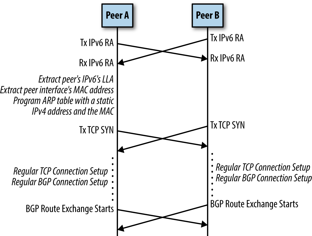
Figure 4-1. BGP unnumbered packet timeline sequence
After a connection has been successfully established, BGP receives a route advertisement for the aforementioned 10.1.1.0/24 from the peer with the peer’s IPv6 LLA (and global IPv6 address if one is configured). If BGP selects this path as the best path to reach 10.1.1.0/24, it passes this route down to the Routing Information dataBase (RIB) process (called zebra in FRRouting), with the nexthop set to the IPv6 LLA, this nexthop information being received in the BGP UPDATE message.
Note
RIB is a collection of all routes received from every routing protocol running on the node and statically configured routes. If there are multiple announcers for a route, the RIB process picks one with the lowest value of a field called distance. There are default values for distance for each protocol, but the user can change them, as well.
On receiving a route for 10.1.1.0/24 with an IPv6 LLA, assume that the RIB picks this as the best route with which to populate the forwarding table. The RIB process now consults its database to see whether it has the information for the MAC address associated with this IPv6 LLA. Let this MAC address be 00:00:01:02:03:04. The RIB process now adds a static ARP entry for 169.254.0.1 with this MAC address, pointing out the peering interface. 169.254.0.1 is an IPv4 LLA, although it is not automatically assigned to an interface the way IPv6 LLA is. FRRouting assumes that 169.254.0.1 is reserved (as of this writing, this cannot be changed through a configuration option). The reason for the static ARP entry is so that the router cannot run ARP to get this address; this IP address was assigned by the router implicitly without its neighbor knowing anything about this assignment; thus, the neighbor cannot respond to the ARP, because it doesn’t have the IP address assigned to the interface.
The RIB process then pushes the route into the kernel routing table with a nexthop of 169.254.0.1 and an outgoing interface set to that of the peering interface. So, the final state in the tables looks like this:
ROUTE: 10.1.1.0/24 via 169.254.0.1 dev swp1
ARP: 169.254.0.1 dev swp1 lladdr 00:00:01:02:03:04 PERMANENT
At this point, everything is set up for packet forwarding to work correctly. More specifically, the packet forwarding logic remains unchanged with this model.
If the link goes down or the remote end stops generating an RA, the local RA process yanks out the LLA and its associated MAC from the RIB. This causes the RIB process to decide that the nexthop is no longer reachable, which causes it to notify the BGP process that the peer is no longer reachable. RIB also tears down the static ARP entry that it created. Terminating the session causes BGP to yank out the routes pointing out this peering interface.
To summarize:
BGP unnumbered uses the interface’s IPv6 LLA to set up a BGP session with a peer.
The IPv6 LLA of the remote end is discovered via IPv6’s Router Advertisement (RA) protocol.
RA provides not only the remote end’s LLA, but also its corresponding MAC address.
BGP uses RFC 5549 to encode IPv4 routes as reachable over an IPv6 nexthop, using the IPv6 LLA as the nexthop.
The RIB process programs a static ARP entry with a reserved IPv4 LLA, 169.254.0.1, with the MAC address set to the one learned via RA.
BGP hands down to the RIB process IPv4 routes with the IPv6 LLA as the nexthop.
The RIB process converts the nexthop to 169.254.0.1 and the outgoing interface before programming the route in the forwarding table.
BGP Capability to Negotiate RFC 5549 Use
Because encoding IPv4 routes with an IPv6 nexthop is not the usual model, RFC 5549 defines a new capability, called extended nexthop, to negotiate the use of RFC 5549 over a peering session. As is common with BGP capabilities, both sides must advertise their capability to understand RFC 5549 in order for it to be used in the BGP peering.
FRRouting automatically enables RA on an interface and enables the sending of the extended nexthop BGP capability, when a BGP peering is set up to be based on an interface that does not have an IPv4 address.
Interoperability
Every eBGP peer sets the NEXTHOP to its own IP address before sending out a route advertisement.
Figure 4-2 shows a hypothetical network in which routers B and D support RFC 5549, whereas routers A and C do not. So, there are interface IP addresses on the links between B and A and between B and C. When A announces reachability to 10.1.1.0/24, it provides its peering interface’s IPv4 address as the nexthop. When B advertises reachability to 10.1.1.0/24, it sets its IPv6 LLA as the nexthop when sending the route to D, and sets its interface’s IPv4 address as the nexthop when sending the route to C.
In the reverse direction, if D announces reachability to a prefix 10.1.2.0/24, it uses its interface’s IPv6 LLA to send it to B. When B announces this to A and C, it sets the nexthop to be that of the IPv4 address of the peering interface.
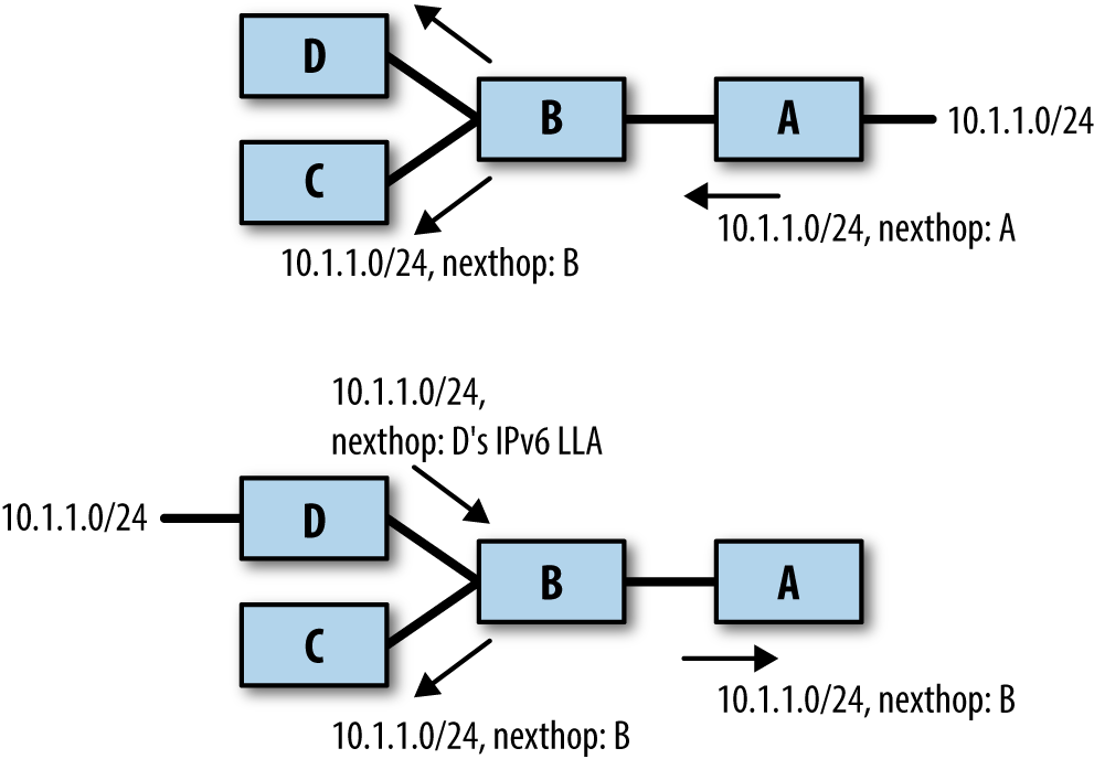
Figure 4-2. Interoperability with RFC 5549
A remote-as By Any Other Name
After eliminating interface addresses, the only thing remaining to accomplish the goal of the simple, cookie-cutter configuration is the need to specify the neighbor’s ASN via the remote-as keyword of a BGP neighbor configuration.
There are two primary uses for specifying neighbor’s ASN in the neighbor specification:
In the spirit of connecting across administrative domains, and where harm on a large financial and global scale is possible by connecting to the wrong administrative domain accidentally, it is critical to verify operator intent.
To identify whether the BGP session will be governed by iBGP rules or eBGP rules.
Within the data center, because we’re not crossing administrative domains, security is no longer a compelling reason to specify the ASN. And, if the only reason is to identify what rules govern the session, that can be done by a simple non-neighbor-specific field.
Based on this reasoning, FRRouting added two new choices to the remote-as keyword: external and internal. “External” means that you expect to set up an eBGP connection with this neighbor, whereas “internal” means that you expect to set up an iBGP connection. In reality, you can even ignore this specification because you can identify iBGP versus eBGP by the ASN received in the BGP OPEN message. However, the remote-as command helps kick off creation of the BGP peer data structure, as it’s easy to make a typo in the neighbor specification in one of the commands and accidentally create a new BGP peer. For example, if there were a peer169.254.1.11 and there was a typo in one of the neighbor commands—neighbor 169.254.11.1 timers connect 9 instead of neighbor 169.254.1.11 timers connect 9—you don’t want BGP to begin spinning up a new neighbor session.
Summary
By eliminating interface IP addresses and the specification of the exact remote-as in the neighbor command specification, we can arrive at a configuration, listed in Example 4-1, that looks remarkably similar across the leaves and spines illustrated in Figure 3-1. The only differences between the nodes are shown in bold in the example.
Example 4-1. Final BGP configuration for a leaf and spine in a Clos network
// leaf01 configuration

log file /var/log/frr/frr.log
ip prefix-list DC_LOCAL_SUBNET 5 permit 10.1.0.0/16 le 26
ip prefix-list DC_LOCAL_SUBNET 10 permit 10.0.254.0/24 le 32
route-map ACCEPT_DC_LOCAL permit 10
  match ip-address DC_LOCAL_SUBNET

router bgp 65000
  bgp router-id 10.0.254.1
  neighbor peer-group ISL
  neighbor ISL remote-as external
  neighbor swp51 interface peer-group ISL
  neighbor swp52 interface peer-group ISL
  address-family ipv4 unicast
    neighbor ISL activate
    redistribute connected route-map ACCEPT_DC_LOCAL

// spine01 configuration

log file /var/log/frr/frr.log
ip prefix-list DC_LOCAL_SUBNET 5 permit 10.1.0.0/16 le 26
ip prefix-list DC_LOCAL_SUBNET 10 permit 10.0.254.0/24 le 32
route-map ACCEPT_DC_LOCAL permit 10
  match ip-address DC_LOCAL_SUBNET

router bgp 65534
  bgp router-id 10.0.254.254
  neighbor peer-group ISL
  neighbor ISL remote-as external
  neighbor swp1 interface peer-group ISL
  neighbor swp2 interface peer-group ISL
  neighbor swp3 interface peer-group ISL
  neighbor swp4 interface peer-group ISL
  address-family ipv4 unicast
    neighbor ISL activate
    redistribute connected route-map ACCEPT_DC_LOCAL
This is a far cry from the original node-specific BGP configuration. The configuration is also extremely trivial to automate using tools such as Ansible, Puppet, or Chef. This is due not only to the elimination of just about every router-specific information via the use of interface names, but also, more important, each router’s configuration contains information that is completely local to the router, with no information about the peer.
We’ve so far focused on configuring BGP in a Clos topology. We have not described how to view the results of our configuration, manage BGP after the initial configuration, or how to configure BGP to connect a Clos topology to the external world. These are the focus of Chapter 5.
Get BGP in the Data Center now with the O’Reilly learning platform.
O’Reilly members experience books, live events, courses curated by job role, and more from O’Reilly and nearly 200 top publishers.

