Arduino I/O Demystified
The Arduino interface board has a single row of connectors or pins on each side of the board. These are used mostly for inputs, outputs, and power. Figure 5-1 shows a simple illustration of the Arduino Uno interface board. Your board might be a little different.
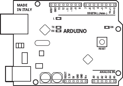
Figure 5-1. Arduino illustration
As shown in Figure 5-1 and printed on the interface board, there are 14 pins on one side of the board marked Digital that are numbered from 0 to 13. Of these, two are used for serial communications through USB for programming, debugging, and other forms of communication. These pins are numbered 0 and 1, and are marked RX <- and ...
Get Beginning Arduino Programming now with the O’Reilly learning platform.
O’Reilly members experience books, live events, courses curated by job role, and more from O’Reilly and nearly 200 top publishers.

