Reducing the structure of a multidimensional, dynamic system into a linear narrative form is always a challenge, whether we are communicating our vision of a system that doesn’t exist or trying to explain the interacting parts of one that we’ve already built. Hypertext might make it easier to approach the elephant from several perspectives, but paper doesn’t yet support hyperlinks very well.
As we look at each of these facets, keep in mind that they are different ways of looking at the overall system. For instance, we used a modular architecture to support different deployment scenarios. At the same time, each module is built in a layered architecture. These are orthogonal but intersecting concerns. Each set of modules follows the same layering, and each layer is found across all the modules.
Indeed, we all felt deeply gratified that we were able to keep these concerns separated while still making them mutually supportive.
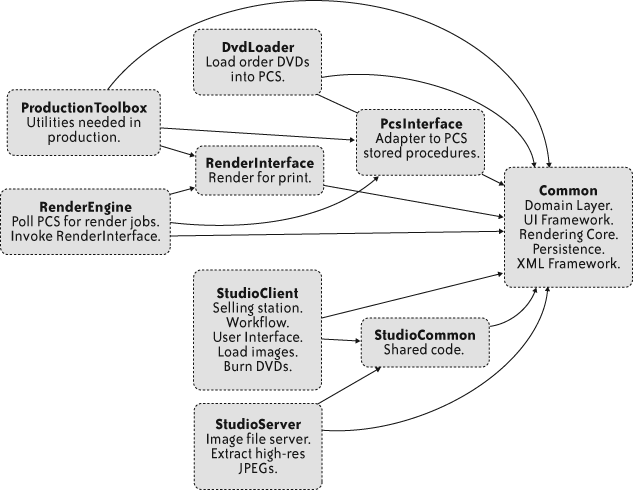
All along, we were thinking “product family” rather than “application” because we had to support several different deployment scenarios with the same underlying code. In particular, we knew from the beginning that we would have the following configurations:
- Studio Client
A studio has between two and four of these workstations. The photographers use them for the entire workflow, from loading images through to creating the orders.
- Studio Server
The central server inside each studio runs MySQL for structured data such as customers and orders. The server also has much more robust storage than the workstations, using RAID for resiliency. The studio server also burns the day’s orders to DVD.
- Render Engine
Once in production, we decided to build our own render engine. By using the same code for rendering to the screen in the studio and to the print-ready images in production, we could be absolutely certain that the customer would get what they expected.
At first, we thought these different deployment configurations would just be different collections of .jar files. We created a handful of top-level directories to hold the code for each deployment, plus one “Common” folder. Each top-level folder has its own source, test, and bin directories.
It didn’t take long for us to become frustrated with this structure. For one thing, we had one giant /lib directory that started to accumulate a mixture of build-time and runtime libraries. We also struggled with where to put noncode assets, such as images, color profiles, Hibernate configurations, test images, and so on. Several of us also felt a nagging itch over the fact that we had to manage .jar file dependencies by hand. In those early days, it was common to find entire packages in the wrong directory. At runtime, though, some class would fail to load because it depended on classes packaged into a different .jar file.
The breaking point came when we introduced Spring[9] about three iterations into the project. We were following an “agile architecture” approach: keep it minimal and commit to new architecture features only when the cost of avoiding them exceeds the cost of implementing them. That’s what Lean Software Development calls “the last responsible moment.” Early on, we had only a casual knowledge of Spring, so we chose not to depend on it, though we all expected to need it later.
When we added Spring, the .jar file dependency problems were multiplied by configuration file problems. Each deployment configuration needs its own beans.xml file, but well over half of the beans would be duplicated between files—a clear violation of the “don’t repeat yourself” principle[10]—and a sure-fire source of defects. Nobody should have to manually synchronize bean definitions in thousand-line XML files. And, besides, isn’t a multi-thousand-line XML file a code smell in its own right?
We needed a solution that would let us modularize Spring beans files, manage .jar file dependencies, keep libraries close to the code that uses them, and manage the classpath at build time and at runtime.
Learning Spring is like exploring a vast, unfamiliar territory. It’s the NetHack of frameworks; they thought of everything. Wandering through the javadoc often yields great rewards, and in this case we hit pay dirt when I stumbled across the “application context” class.
The heart of any Spring application is a “bean factory.” A bean factory allows objects to be looked up by name, creates them as needed, and injects configurations and references to other beans. In short, it manages Java objects and their configurations. The most commonly used bean factory implementation reads XML files.
An application context extends the bean factory with the crucial ability to make a chain of nested contexts, as in the “Chain of Responsibility” pattern from Design Patterns (Gamma et al. 1994).
The ApplicationContext object gave us
exactly what we needed: a way to break up our beans into multiple
files, loading each file into its own application context.
Then we needed a way to set up a chain of application contexts, preferably without using some giant shell script.
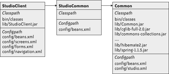
Thinking of each top-level directory as a module, I thought it would be natural to have each module contain its own metadata. That way the module could just declare the classpath and configuration files it contributes, along with a declaration of which other modules it needs.
I gave each module its own manifest file. For example, here
is the manifest file for the StudioClient module:
Required-Components: Common StudioCommon
Class-Path: bin/classes/ lib/StudioClient.jar
Spring-Config: config/beans.xml config/screens.xml config/forms.xml
        config/navigation.xml
Purpose: Selling station. Workflow. User Interface. Load images. Burn DVDs.
This format clearly derives from .jar file manifests. I found it useful to align the mental function “manifest file” with a familiar format.
Notice that this module uses four separate bean files. Separating the bean definitions by function was an added bonus. It reduced churn and contention on the main configuration files, and it provided a nice separation of concerns.
Our team strongly favored automatic documentation, so we built several reporting steps into the build process. With all the module dependencies explicitly written in the manifest files, it was trivial to add a reporting step to our automated build. Just a bit of text parsing and a quick feed to Graphviz generated the dependency diagram in Figure 4-2.
With these manifest files, we just needed a way to parse them and do something useful. I wrote a launcher program, imaginatively called “Launcher,” to do just that.
I’ve seen many desktop Java applications that come with huge shell or batch scripts to locate the JRE, set up environment variables, build the classpath, and so on. Ugh.
Given a module name, Launcher parses the manifest files,
building the transitive closure of that module’s dependencies.
Launcher is careful not to add a module twice, and it resolves the
set of partial orderings into a complete ordering. Figure 4-3 shows the
fully resolved dependencies for StudioClient. StudioClient declares both StudioCommon and Common as dependencies, but Launcher
gives it only one copy of each.
To avoid classpath “pollution” from the host environment—ANT on a build box, or the JRE classpath on a workstation—Launcher builds its own class loader from the combined classpaths. All application classes get loaded inside that class loader, so Launcher uses that class loader to instantiate an initializer. Launcher passes the configuration path into the initializer, which creates all the application context objects. Once the application contexts are constructed, we’re up and running.
Throughout the project, we refactored the module structure several times. The manifest files and Launcher held up with only minor changes throughout. We eventually arrived at six very different deployment configurations, all supported by the same structure.
The modules all share a similar structure, but they don’t have to be identical. That was one of the side benefits of this approach. Each module can squirrel away stuff that other modules don’t care about.
Studio associates are hired for their ability to work well with the camera and the families, especially children, not for their computer skills. At home, they might be Photoshop gurus, but in the studio, nobody expects them to become power users. In fact, during the busy season, a studio might bring on a number of seasonal associates. Consequently, fast ramp-up is critical.
One of the architects also served as our UI designer. He always had a clear vision of the interface, even if we didn’t always agree on how much was feasible to implement. He wanted the user interface to be friendly and visible. There would be no menus. Users would interact with images through direct manipulation. Large, candy-coated buttons made all options visible. In short, the workstation should look like a kiosk.
That left the decision about what technology to use for the display itself.
One of our team made a survey of the Java rich UI technologies available, mainstream and fringe. We hoped to find a good declarative UI framework, something to help us avoid an endless slog through Swing tweaks. The results shocked us all.
In 2005, even after a decade of Java, two basic choices dominated the mainstream: XML hell or GUI builder spaghetti. The XML variants map more or less directly from Swing components to XML entities and attributes. This made no sense to us. GUI changes require a code release, whether the changes are implemented in straight Java code or in XML files. Why keep two languages in your head—Java plus the XML schema—instead of just Java? Besides, XML makes a clumsy programming language.
GUI builders had burned all of us before. Nobody wanted to end up with business logic woven into action listeners embedded in JPanels.
Reluctantly, we settled on a pure Swing GUI, but with some ground rules. Over a series of lunches at our local Applebee’s, we hashed out a novel way of using Swing without getting mired in it.
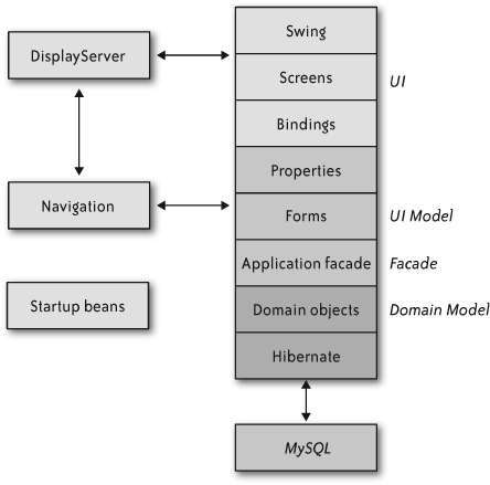
The typical layered architecture goes “Presentation,” “Domain,” and “Persistence.” In practice, the balance of code ends up in the presentation layer, the domain layer turns into anemic data containers, and the persistence layer devolves to calls into a framework.
At the same time, though, some important information gets
duplicated up and down the layers. For instance, the maximum length
of a last name will show up as a column width in the database,
possibly a validation rule in the domain, and as a property setting
on a JTextField in the UI.
At the same time, the presentation embeds logic such as “if this checkbox is selected, then enable these four other text fields.” It sounds like a statement about the UI, but it really captures a bit of business logic: when the customer is a member of the Portrait Club, the application needs to capture their club number and expiration date.
So within the typical three-layer architecture, one type of information is spread out across layers, whereas another type of important information is stuck inside GUI control logic.
Ultimately, the answer is to invert the GUI’s normal relationship to the domain layer. We put the domain in charge by separating the visual appearance of a screen from the logical manipulation of its values and properties.
In this model, a form object presents one or more domain objects’ attributes as typed properties. The form manages the domain objects’ lifecycles as well as calling down to the facades for transactions and persistence. Each form represents a complete screen full of interacting objects, though there are some limited cases where we use subforms.
The trick, though, is that a form is completely nonvisual. It doesn’t deal with UI widgetry, only with objects, properties, and interactions among those properties. The UI can bind a Boolean property to any kind of UI representation and control gesture: checkbox, toggle button, text entry, or toggle switch. The form doesn’t care. All it knows is that it has a property that can take a true/false value.
Forms never directly call screens. In fact, most of them don’t even know the concrete class of their screens. All communication between forms and screens happens via properties and bindings.
Unlike typical form-based applications, the
properties that a Form exposes are not just
Java primitives or basic types like java.lang.Integer. Instead, a Property contains a value together with
metadata about the value. A Property can answer whether it is
single-valued or multivalued, whether it allows null values, and
whether it is enabled. It also allows listeners to register for
changes.
The combination of Forms and their
Property objects gave us a clean model of the
user interface without yet dealing with the actual GUI widgetry.
We called this layer the “UI Model” layer, as shown in Figure 4-4.
Each subclass of Property works for a
different type of value. Concrete subclasses have their own
methods for accessing the value. For instance, StringProperty has getStringValue() and setStringValue(String). Property values
are always object types, not Java primitives, because primitives
do not allow null values.
It might seem that property classes could proliferate
endlessly. They certainly would if we created a property class for
each domain object class. Most of the time, instead of exposing
the domain object directly, the Form would
expose multiple properties representing different aspects of the
domain object. For example, the customer form exposes StringProperty objects for the
customer’s first name, last name, street address, city, and zip
code. It exposes a DateProperty
for the customer’s club membership expiration date.
Some domain objects would be awkward to expose this way.
Connecting a slider that controls dilation of the image or
embedded image in a design to the underlying geometry would have
required more than half a dozen properties. Having the
Form juggle this many properties just to drag a
slider seemed like a pretty clear code smell. On the other hand,
adding another type of property seemed like the path to wild type
proliferation.
Instead, we compromised and introduced an object property to hold arbitrary Java objects. The animated discussion before that class appeared included the phrases “slippery slope” and “dumping ground.” Fortunately, we kept that impulse in check—one of the perils of a type-checked language, I suppose.
We handled actions by creating a “command property,” which encapsulates command objects but also indicates enablement. Therefore, we can bind command property objects to GUI buttons, using changes in the property’s enablement to enable or disable the button.
The UI Model allowed us to keep Swing contained within the UI layer itself. It also provided huge benefits in unit testing. Our unit tests could drive the UI Model through its properties and make assertions about the property changes resulting from those actions.
So, forms are not visual themselves, but they expose named, strongly typed properties. Somewhere, those properties must get connected to visible controls. That’s the job of the bindings layer.
Whereas properties are specific to the types of
their values, bindings are specific to individual Swing
components. Screens create their own components, and then register
bindings to connect those components to the properties of the
underlying Form objects. An individual screen
does not know the concrete type of form it works with, any more
than a form knows the concrete type of the screen that attaches to
it.
Most of our bindings would update their properties on every GUI change. Text fields would update on each keystroke, for instance. We used that for on-the-fly validation to provide constant, subtle feedback, rather than letting the user enter a bunch of bad data and then yelling at them with a dialog box.
Bindings also handle conversion from the property’s object type to a sensible visual representation for their widgets. So, the text field binding knows how to convert integers, Booleans, and dates into text (and back again). Not every binding can handle every value type, though. There’s no sensible conversion from an image property to a text field, for example. We made sure that any mismatch would be caught at application startup time.
An interesting wrinkle developed after we had built the first iteration of this property-binding framework. The first screen we tried it out on was the customer registration form. Customer registration is fairly straightforward, just a bunch of text fields, one checkbox, and a few buttons. The second screen, the album screen, is much more visual and interactive. It uses numerous GUI widgets: two proof sheets, a large image editor, a slider, and several command buttons. Even here, the form makes all the real decisions about selections, visibility, and enablement entirely through its properties. So the album form knows that the proof sheets’ selections affect the central image editor, but the screen is oblivious. Keeping the screens “dumb” helped us eliminate GUI synchronization bugs and enabled much stronger unit testing.
Although it takes a long time to explain the property-binding architecture, I still regard it as one of the most elegant parts of Creation Center. By its nature, Creation Center is a highly visual application with rich user interaction. It’s all about creating and manipulating photographs, so this is no gray, forms-based business application! Yet, from a small set of straightforward objects, each defined by a single behavior, we composed a very dynamic interface.
The client application eventually supported drag-and-drop, subselections inside an image, on-the-fly resizing, master-detail lists, tables, and double-click activation. And we never had to break out of the property-binding architecture.
There’s a classic pitfall in building a strong domain model. The presentation layer—or in this case, the UI Model—often gets too intimate with the domain model. If the presentation traverses relationships in the domain, then it becomes difficult to change the domain model. Like any agile team, we needed to stay flexible, and there was no way we would make design choices that would lead to less flexibility over time.
Martin Fowler’s “Application Facade” pattern fit the bill (see the References” section at the end of this chapter). An application facade presents only a portion of the domain model to the presentation layer. Instead of walking through graphs of domain objects, the presentation asks the application facade to assist with traversal, life cycle, activation, and so on.
Each form defined a corresponding facade interface. In fact, following the dictum that consumers—rather than their providers—should define interfaces we put the facade interface in the form’s package. The form asks the facade to look up domain objects, relate them, and persist them. In fact, the facades managed all database transactions, so the forms were never aware of transaction boundaries.
The interfaces at this boundary, between forms and facades, also became an ideal place to isolate objects for unit testing. To test a particular form, the unit test creates a mock object that implements the facade’s interface. The test trains the mock object to feed the form with some set of expected results, including error conditions that would be very difficult to reproduce with the real facade. I think we all regarded mock objects as a two-sided compromise: although they made unit tests possible, something still felt wrong about tying the tests so closely to the forms’ implementations. For example, mock objects have to be trained with the exact sequence of method calls to expect, and the exact parameters. (Newer mock object frameworks are more flexible.) As a result, changes in the internal structure of the forms would cause tests to fail, even though no externally visible behavior changed. To a certain extent, this is just the price you pay for using mock objects.
All the Creation Center applications, both in the studio and in the printing facility, used the same stack of layers. Removing the GUI from the driver’s seat kept the team from spending endless cycles in Swing tweaking. This inversion of control also provided a uniform structure that every application, and every pair, could follow. Even though we created more than the usual “three-layer cake,” our stack was quite effective at separating concerns: Swing was limited to the UI, domain interaction in the forms, and persistence in the facades.
When a photographer finishes a session, she grabs any open workstation. Depending on how busy the studio is, she’ll usually finish with the customer at that time. It’s common, though, for customers to come back later, maybe even on a different day. It would be ridiculous to permanently attach a customer to a single workstation—not just unworkable for scheduling, but also risky. Workstations break!
So any workstation in the studio must be interchangeable, but “interchangeable” presents some problems. The images for a single session can consume close to a gigabyte.
We briefly contemplated building the workstations as a peer-to-peer network with distributed replication. Ultimately, we opted for a more traditional client-server model, as shown in Figure 4-5.
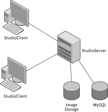
The server is equipped with larger disks than the clients, and they are RAIDed for resilience. The server runs a MySQL database to hold structured data about customers, sessions, and orders. Most of the space, however, is devoted to storing the customers’ photographs.
Because the studios are remote and the associates are not technically adept, we knew it would be important to make the “plumbing” invisible. Associates should never have to look at filesystems, investigate failures, or restart jobs. They should certainly never log into the database server! At worst, if a network cable should be bumped loose, once it is plugged back in, everything should work as normal and also should automatically recover from that temporary problem.
With that end in mind, we approached the system and application architecture.
To make the workstations interchangeable, the most essential feature would be automatic transfer of images, both from the workstation where the photographer loaded them to the server and from the server to another workstation.
The studio client and studio server both use a central component called an image repository. It deals with all aspects of storing, loading, and recording images, including their metadata. On the client side, we built a local, caching, write-behind proxy. When a caller asks for an image, this client image repository either returns it directly from local cache or downloads the file into local cache, and then returns it. Either way, callers remain blissfully ignorant.
Likewise, when adding images on the client, the client image repository uploads it to the server. We use a pool of threads to run background transfers so the user doesn’t have to wait on uploads.
Both the client and server repositories are heavily multithreaded. We created a system of locking called “reservations.” Reservations are a soft form of collaborative locking. When a client wants to add an image to the repository, it must first request and hold a “write reservation.” This way, we can be sure that no other thread is reading the image file when we issue the reservation. Readers have to acquire a “read reservation,” naturally.
Although we did not implement distributed transactions or two-phase commit, in practice there is only a small window between when the client image repository grants a write reservation and when the server side grants a corresponding write reservation. When that second reservation is granted, we can be confident that we will avoid file corruption.
In practice, even lock contention is rare. It requires two photographers at two different workstations to access exactly the same customer’s session. Still, there are several workstations in every studio, and each workstation has many threads, so it pays to be careful.
Obviously, that leaves the problem of getting the images from the client to the server. One option we considered and rejected early was CIFS—Windows shared drives. Our main concern here was fault-tolerance, but transfer speed also worried us. These machines needed to move a lot of data back and forth, while photographers and customers were sitting around waiting.
In our matrix of off-the-shelf options, nothing had the right mix of speed, parallelism, fault-tolerance, and information hiding. Reluctantly, we decided to build our own file transfer protocol, which led us into one of the most complex areas of Creation Center. Image transfer became a severe trial, but we emerged, at last, with one of the most robust features of the whole system.
I had some prior experience with Java NIO, so I knew we could use it to build a blazing-fast image transfer mechanism. Building the NIO data transfer itself wasn’t particularly difficult. We used the common leader-follower pattern to provide concurrency while still keeping NIO selector operations on a single thread.
Although the protocol wasn’t difficult to implement, there were a number of nuances to deal with:
Either end can close a socket, particularly if the client crashes. Sample code never deals with this properly.
While handling an IO event, the
SelectionKeywill still signal that it’s ready. This can result in multiple threads calling into the same handler if you don’t clear that operation from the key’s interest set.The leader must perform all changes to a
SelectionKey’s interest set or else you get race conditions with theSelector, so we had to build a queue of pendingSelectionKeychanges that the leader thread would execute before calling select.
Handling these tricky details led to quite a bit more coupling between the various objects than I initially expected. If we had been building a framework, this whole area would have needed much more attention to loose coupling. For an application, however, we felt it was acceptable to regard the collection of collaborating objects in the server as a cohesive unit.
One particularly interesting effect showed up only when we ran a packet sniffer to see if we were really getting the maximum possible throughput. We weren’t. At first, when the reactor read from a socket that had data available, it would read one buffer full and then return. We figured that it wouldn’t take very long to get back around the loop if more than 8,192 bytes were available. It turns out that the studio network is fast enough to fill the server’s TCP window before the next thread could get back into the handler, so virtually every transfer would stall for about half of the total transfer time. We added a loop inside the reactor, so it would keep reading until the buffer was drained. That cut the transfer time by nearly half, and reduced the amount of overhead in threading and dispatching. I found this particularly interesting because it works only for fast networks with low latency and only if the total number of clients is small. With higher network latency or more clients, looping that way would risk starving some clients. Again, it was a trade-off that made sense in our context.
I knew it wouldn’t be hard at all to build something fast but fragile. The real challenge would be making it robust, especially when the whole network would exist in a studio hundreds of miles away. One with no ability to log in remotely to debug problems or clean up after failures. One with small children, distracted parents, and servers sitting at toddlers’ eye level. Talk about a hostile environment! Moving bits across the wire would not be enough; we needed atomic file transfer with guaranteed delivery.
The first layer of defense was the protocol itself. For a
“put” operation—uploading a file from client to server—the first
packet of the request includes the file’s MD5 checksum. Once the
client sends the last packet, it waits for a response from the
server. The server responds with one of several codes: OK, TIMEOUT, FAILED_CHECKSUM, or UNKNOWN_ERROR. On anything but an
OK, the client resends the
entire file in what we call a “fast retry.” The client gets three
fast retries before the transfer fails.
Problems with file transfer will come in two varieties. One type is the “fast transient,” a quick problem that will clear itself up, such as network errors. The other type requires human intervention. That means problems will either be cleared up in a few milliseconds, or they will take minutes to hours to correct. There’s no point in retrying a fast file transfer over and over again. If it didn’t work after the first few attempts, it’s not likely to work for quite a while.
Therefore, if the client exhausts all the fast retries, it puts the file transfer job in a queue. A background job wakes up every 20 minutes looking for pending file transfer jobs. It tries each job again, and if it fails again, it goes right back into the queue. Using Spring’s scheduling support made this “slow retry” almost trivial to implement.
This mix of fast and slow retries lets us decouple maintenance and support on the server from the clients. There’s no need to “cold boot” an entire studio for upgrades or replacements.
The local and remote image repository and their associated file transfer mechanics became a seriously tough slog. Once it was done, though, the whole thing could upload images to the server faster than they could be read from the memory card. Downloading them on another machine was fast enough that users never perceived any activity at all. The client would download all the thumbnails for an album during the transition from one screen to the next. Downloading the screen-sized images for full-size display could be done during a mouse click. This speed let us avoid the user frustration of “loading” dialogs.
Imagine operating 600 remote database servers across four time zones. They might as well be on a desert island, and digitally speaking, they are. If a database administrator needed to apply changes by hand, he would have to travel to hundreds of locations.
In such circumstances, one option would be to get the database design exactly right before the first release, and then never change it again. There may still be a few people who think that’s possible, but certainly none of them were on my team. We expected and even counted on change at every level, including the database.
Another option would be to send release notes out to the
field. The studio managers always called the service desk for a
verbal walkthrough when they executed the installs. Perhaps we could
include SQL scripts in documents on the release CDs for them to type
in or copy-and-paste. The prospect of dictating any command that
starts with, “Now type mysqladmin –u root –p...”
gives me cold sweats.
Instead, we decided to automate database updates. Ruby on Rails calls these “database migrations,” but in 2005 it wasn’t a common technique.
The studio server defines a bean called a database updater. It keeps a list of database update objects, each representing an atomic change to the database. Each database update knows its own version and how to apply itself to the database.
At startup time, the database updater checks a table for the current version of the database. If it doesn’t find the table, it assumes that no updates exist or have been applied. Accordingly, the very first update bootstraps the version table and populates it with one row. That single row contains a version number and a lock field. To avoid concurrent updates, the database updater first updates this row to set the lock field. If it cannot, then it assumes some other machine on the network is already applying updates.
We used this migration ability to apply some simple changes and some sophisticated ones. One of the simple ones just added indexes to a couple of columns that were affecting performance. One of the updates that made us really nervous changed all the table types from MyISAM to InnoDB. (MyISAM, the default MySQL table type, does not support transactions or referential integrity. InnoDB does. If we had known that before our first release, we could have just used InnoDB in the first place.) Given that we had deployed databases with production data, we had to use a sequence of “alter table” statements. It worked beautifully.
After a few releases had gone out to the field, we had about 10 updates. None of them failed.
Every time we run a build, we reset the local development database to version zero and roll forward. That means we exercise the update mechanism dozens of times every day.
We also unit test every database update. Each test case makes some assertions about the state of the database prior to the update. It applies the update and then makes some assertions about the resulting state.
Still, these tests all work with “well-behaved” data. Weird things happen out in the field, though, and real data is always messier than any test data set. Our updates create tables, add indices, populate rows, and create new columns. Some of these changes can break badly if the data isn’t what we expect. We worried about the risky time during the updates and looked for ways to make the process more resilient.
Suppose something goes wrong with one of the updates. A studio could be shut down until Operations found a way to restore the database, and if the update really goes wrong, it might leave the database corrupted or in some intermediate state. Then the studio wouldn’t even be able to roll back to the previous version of the application. To avoid that disaster scenario, the database updater makes a backup copy of the database before it starts applying the updates. If it can’t make the backup copy, then it halts the update process.
If errors occur during the updates, the updater automatically attempts to reload from that backup copy. If even that step fails, well, at least there’s a copy onsite so a support technician can talk the studio manager through a manual restore.
In fact, in the absolute worst case, the printing facility always has a copy of the database that’s no more than one day old. We used some of the extra space on the daily DVD to send a complete copy of the database every day. There’s something to be said for a small database and a lot of storage space.
The time we invested in automated database updates paid off in several ways. First, we improved performance and reliability through some early updates. Feedback from the user community was immediate and positive after that release. Second, the operations group greatly appreciated the easy deployment of new releases. Previous systems had required the studios to ship removable hard drives back and forth, with all the attendant logistics problems. Finally, having the update mechanism allowed us to focus on “just sufficient” database design. We did not peer into the crystal ball or overengineer the database schema. Instead, we just designed enough of the schema to support the current iteration.
In working with customers, the studio associate creates some compositions that use multiple photographs, inset into a design. These designs come from a design group at company headquarters. Some designs are perennial, others are seasonal. Christmas cards in a wide variety of designs are a big seller, at least in the weeks before Christmas. Not surprisingly, demand drops precipitously after that.
A particular design includes some imagery for the background and a description of how many openings there are for base images, and the geometry of those openings. The associate can be very creative in filling those openings with photographs and with other compositions.
We found some interesting challenges dealing with these designs and the base images that go in them. For instance, what happens when a customer places an order, but then a new version of the design gets rolled out to the studio? At a smaller scale, what do you do if the associate nested one design within another—such as a sepia-tinted photograph inside a border—and then changes or deletes the original design?
At first, this looked like a nightmare of reference counting and hidden linkages. Every scheme we considered created a web of object references that could lead to gaps, missing images, or surprising changes. As a team, we all believed in “The Rule of Least Surprise,” so hidden linkages causing changes to ripple from one product to another just wasn’t going to work.
When our lead visionary came up with a simple, clear answer, it didn’t take more than 30 seconds to sell the rest of us on it. The solution incorporated two rules:
Don’t change anything after creating it. Designs and compositions would be immutable.
Copy, don’t reference, the original.
Taken together, this means that selecting a design actually copies that design into the working space. If the associate adds the resulting composition to the album, it’s actually a complete and self-contained copy of the design that gets added. Likewise, nesting one enhanced image into another makes a copy of the original and grafts it into the new composition. From the moment that graft happens, the original composition and the new one are completely independent of each other.
These copies are not just a trick of object references in memory. The actual XML description of the composition contains a complete copy of the design or the embedded compositions. This description lives in the studio’s database, and it’s the same description that gets sent on the DVD. When the studio manager burns the day’s orders to DVD, the StudioServer packs in everything needed to create the final render: source images, backgrounds, alpha masks, and the instructions about how to combine them into the final image.
Having the complete description of the whole composition—including the design itself—on DVD became a huge advantage for production.
Previous systems kept the designs in a library, and orders just referenced them by ID. That meant the designers had to coordinate design IDs between the studios and the centralized printing facility. Therefore, designs had to be “registered” in production before they could be rolled out to the field. Should the IDs get out of sync, as sometimes happened, the wrong design would be produced and customers would not get the products they expected. Likewise, whenever the designers updated a design, there would be a few days’ worth of DVDs in the pipeline made with the old version of the design. Sometimes it would come out OK, and sometimes it wouldn’t.
Under the new system, designs never have to be registered. Whatever comes through in the XML is what gets produced, which frees the designers to make much more frequent changes and roll them out however they want. New revisions of designs don’t affect orders in the pipeline, because each order is self-contained. Once the new revision gets out to the studios, then it starts showing up in the order stream.
The only parts that weren’t copied were the image files themselves. They’re too large to copy, and so instead we assign every image—whether part of a design or taken in the studio—its own GUID. As a rule, once something gets a GUID, it is officially immutable. When it’s getting ready to burn orders to DVD, the StudioServer walks through the orders collecting GUIDs (using the controversial Visitor pattern). It adds every image it finds to the DVD, including both the customers’ photographs and the design backgrounds.
The StudioClient helps associates create enhanced portraits from the basic images. Those enhanced portraits can be as simple as a sepia or black and white effect to make the portrait look more dramatic, or they can be as complex as a multilayered structure with alpha-composited backgrounds, text, and soft focus. Whatever the effect, the workstations in the studio do not produce the final rendered image. The printing facility has a variety of printers, supporting different sizes and resolutions. They’re free to change printers or move jobs between printers at any time. The studios just don’t know enough to produce the print-ready images.
When those daily DVDs arrive, they get loaded into the production control system (PCS). PCS makes all the decisions about when to render the images for an order, when to print them, and what printers to send them to. A separate team, in a separate location and in a separate time zone, develops PCS. Previous projects had run into tremendous friction when trying to integrate too closely with PCS. All parties worked with good intentions, but the communication difficulty slowed both teams down. We needed to avoid that friction, and so we decided to apply Conway’s Law (defined in the next section) proactively, by explicitly creating an interface in the software where we knew the team boundary would be.
Conway’s Law is often invoked after the fact, to explain what might otherwise appear to be arbitrary divisions within a product. It speaks to a fundamental truth about development teams: anywhere there is a team boundary, you will find a software boundary. This emerges from the need to communicate about interfaces.
We felt it was important enough to keep the DVD format and layout under complete control of Creation Center that we added a program to our own scope: the DvdLoader. DvdLoader runs in the production facility, reading DVDs and calling various stored procedures within PCS to add orders, compositions, and images. PCS treats the composition instructions as an opaque string, and we were careful to avoid any decisions that would have PCS “opening up” the XML in that string. That sometimes means we duplicate information, such as dependencies on the base images themselves, but that is an acceptable trade-off for maintaining a clear boundary.
Similarly, we defined an interface that let the RenderEngine pull render jobs from PCS while keeping the XML description of the rendering itself under Creation Center’s control.
We worked out written specifications of those interfaces, and then used FIT running on our development server to “nail down” the precise meaning. In effect, we used FIT as an executable specification of the interfaces. That turned out to be vital because even the people who negotiated the interface still found discrepancies between what they thought they agreed to and what they actually built. FIT let us eliminate those discrepancies during development rather than during integration testing, or worse, in production.
The DvdLoader program, which runs in the
printing facility, is really a batch processor that reads orders
from DVDs and loads them into PCS. As with everything else, we
focused on robustness. DvdLoader reads an
entire order, verifying that the DVD includes all the constituent
elements, before it adds the order to PCS. That way it doesn’t
leave partial or corrupted orders in the database.
Because images can appear on many DVDs, the loader checks to see whether there’s already an image loaded with that GUID. If not, the loader adds it. Orders can therefore be resent from the studio whenever necessary, even if PCS has already purged the order and its underlying images. This also means that the background images used in a design get loaded the first time an order for that design arrives.
The DVDs are therefore self-contained and idempotent.
For the render engine itself, we drew on the classic pipes and filters architecture. “Pipeline” is a natural metaphor for rendering images, and separating the complex sequence of actions into discrete steps also made unit testing simple.
On pulling a job from PCS, the render engine creates a
RenderRequest. It passes the
RenderRequest into the
rendering pipeline, where each stage operates on the request
itself. One of the final stages in the pipeline saves the rendered
image to the path specified by PCS. By the time the request exits
the pipeline, it holds only a result object with a success
indicator and an optional collection of problems.
Each step in the pipeline has its own opportunity to report problems by adding an error message to the result. If any step reports errors, the pipeline aborts and the engine reports the problem back to PCS.
Every system has failure modes; the only question is whether you design them in or just let them happen. We took care to design in “safe” failures, particularly in the production process. There was no way we wanted our software to be responsible for stopping the production line.
There’s another aspect, too. When the customer picks up his order, it should be the right one! That is, the product we deliver really needs to match the product the customer ordered. It seems like a trivial statement, but it is very important to render the production scale images in the same way that the on-screen image was rendered. We worked hard to ensure that exactly the same rendering code would be used in production as in the studio. We also made sure that the rendering engine would use the same fonts and backgrounds in production.
In our render engine, we adopted a philosophy of “Fail Fast, Fail Loudly.” As soon as the render engine pulls a job from PCS, it checks through all the instructions, validating that all the resources the job requires are actually available. If the job includes text, the render engine loads the font right away. If the job includes some background images or an alpha mask, the render engine loads the underlying images right away. If anything is missing, it immediately notifies PCS of the error and aborts that job. Out of the 16 steps in the rendering pipeline, the first 5 all deal with validation.
After several months in production, we finally found one error that the render engine didn’t detect early: it didn’t reserve disk space for the rendered image up front. One day when PCS filled its storage volumes, render jobs started to fail late instead of failing early. In all the preceding time, there were no remakes due to bad renders.
Each render engine operates independently. PCS doesn’t keep a roster of the render engines that exist; each engine just pulls jobs from PCS. In fact, engines can be added or removed as needed. Because each engine looks for a new job as soon as it finishes the previous one, we automatically get load balancing, scaled to the horsepower of the individual engines. Faster render engines just consume jobs at a higher rate. Heterogeneous render engines are no problem.
The only bottleneck would be PCS itself. Because the render engines call stored procedures to pull jobs and update status, each render engine generates two transactions every three to five minutes. PCS runs on a decent-sized cluster of Microsoft SQL Server hosts, so it is in no danger of limiting throughput anytime soon.
Get Beautiful Architecture now with the O’Reilly learning platform.
O’Reilly members experience books, live events, courses curated by job role, and more from O’Reilly and nearly 200 top publishers.

