4
Graphical Representations
One ought, every day at least, to hear a little song, read a good poem, see a fine picture, and if it were possible, to speak a few reasonable words.
—Johann Wolfgang von Goethe
Take nothing but pictures. Leave nothing but footprints. Kill nothing but time.
—Motto of the Baltimore Grotto (caving society)
One picture is worth a thousand words.
—Fred R. Barnard
In this chapter we present several methods for representing asynchronous circuits using graphs. While for large designs hardware description languages allow a clearer specification of behavior, graphs are a useful pictorial tool for small examples. They are also the underlying data structure used by virtually all automated analysis, synthesis, and verification tools. Most graphical representation methods can be loosely categorized as either state machine-based or Petri net-based. We present various different types of each and conclude with a description of timed event/level (TEL) structures, which unify some of the key properties of both.
4.1 GRAPH BASICS
In this section we present a brief introduction to basic graph terminology used in this chapter. A graph, G, is composed of a finite nonempty set of vertices, V, and a binary relation R on V (i.e., R ⊆ V × V). A graph can be either undirected or directed.
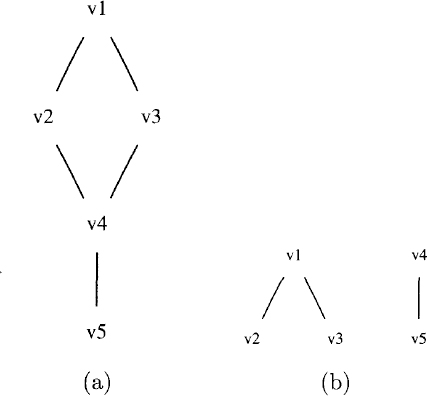
Fig. 4.1 (a) Simple undirected graph. (b) Graph which is not connected.
In an undirected graph, ...
Get Asynchronous Circuit Design now with the O’Reilly learning platform.
O’Reilly members experience books, live events, courses curated by job role, and more from O’Reilly and nearly 200 top publishers.

